Basics of Interrupt Processing
(Original Document)
Overview
To estimate the performance of an interrupt system it is necessary to be aware of all processes that have to be performed from the change of a signal at an input till the change of an output signal triggered by the users interrupt program.
Interrupt Process Flow
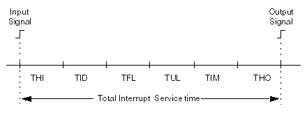
The diagram shows the process involved in an interrupt sequence:
Time
Name
Description
THI
Hardware Input Latency
THI time is defined as the time from the input field connector to the interrupt into theCPU going active.
TID
Interrupt Delay
TID time is defined as the time that firmware is unable to service interrupts. This is done because the CPU maybe communicating with other Quantum modules (I/O,NOM, RIO, etc.).
TFL
Firmware Latency
TFL time is the time that is required to identify source of the interrupt signal.
TUL
User Logic
TUL time is based strictly on the users interrupt program.
TIM
Immediate I/O
TIM time is the time from the output command of the interrupt program to the output module.
THO
Hardware Output Latency
THO time is based on the time from the output of the ASIC to the field connector.
THI
Hardware Input Latency time for the module is
TID
In order to determine the worst case delay time, the module types in the local rack must be known. The worst case time is only based on the module or operation with the longest delay time. The minimum delay is a simple module. See the table below for a listing of Quantum module TID times (worst case).
Quantum module TID times:
Operation
TID (worst case)
Hot swapping an option module
208 μs
Simple module with 4 byte rd/wr transfer*
148 μs
DPM module with 6 byte transfer**
171 μs
User logic editing/power flow display
3-100 μs
Modbus communication
243 μs
CPU Modbus Plus communication
180 μs
NOM communication with Modbus message
208 μs
NOM-like modules***
208 μs
Exceptions to operations—as noted by asterisks—in the table above which lists the Quantum module TID times (worst case).
*
140DDI35300, 140DDO35300, 140DAI54300, 140DAO84210, 140DRC83000, 140HLI34000
**
140ACO02000, 140ACI03000, 140AVI03000, 140AVO02000
***
140CHS11000, 140CRA21X00, 140MMS4250X, 140NOA61100, 140NOE2X100
TFL
The firmware latency time is based on the slot position and how many points are generating interrupts. The following calculation computes the (TFL) for that specific I/O Point.
TFL = 95 μs + (S * 6) μs + (P * 4) μs + (X - 1) μs
with:
S = Slot position of the highest priority interrupting module (1 — 16) P = Highest priority interrupting point (1 — 16) X = Number of input points interrupting
TUL
TUL time is based strictly on the users interrupt program. Listed below is an example case:
Increment counter (on interrupt) = 13 μs
TIM
The time consumed by the immediate I/O handling is basically the execution time of the IMIO_OUT function block. Should the user interrupt routine require additional input signals to be read, the execution time of IMIO_IN. IMIO_IN is not required if the additional inputs are located on the HLI module which generated the interrupt, as all channels of this module are read at itnerrupt time (see also Split Mode).
THO
THO time is based on the time from the output of the ASIC to the field connector.The analysis is based on a Quantum 140DDO35300.
THO time for the 140DDO35300 is: