This mode allows the main application program to be interrupted by a physical real world interrupt signal. This signal stops the Quantum CPU from solving the main logic program, and forces the Quantum CPU to start the event process configured for the respective input. Interrupt input data coming to the Quantum CPU is serviced as it arrives and is read by the Quantum CPU by utilizing hardware handshaking on the backplane system.
Interrupt Logic within the Quantum Processor
Both hardware and timer interrupts are handled within the Quantum CPU in a similar fashion, both systems use Events for the interrupt handler. Within the interrupt handler, the user application program determines what steps need to occur to handle the interrupt. In all cases, within the interrupt handler, if additional inputs need to be read, or outputs need to be written, this is done using the Immediate I/O function blocks IMIO_IN and IMIO_OUT (for detailed information see:
Direct I/O Function Block IMIO_IN and
Direct I/O Function Block IMIO_OUT). The IMIO functionblocks can read or write I/O information from the local backplane. For example, if an interrupt occurred and the logic needs to know the current position residing in the high speed counter module, the IMIO_IN function block would be activated, reading the position asynchronous to scan. This information could then be used in the logic section of the interrupt handler to make some logical decision based on position, and at the end of the routine update a local output module using the IMIO_OUT function block, ending the interrupt handler routine.
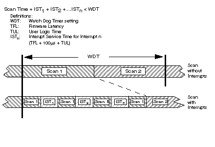
Interrupts may be triggered many times per scan, as is shown in the following diagram, with minimal impact on overall scan for most applications. There are applications however where the scan time is relatively small (10 ms) and the application requires interrupt service every 1 ms. The use of interrupt processing will allow critical sections to be serviced faster than the rest of the overall application, however be aware that you could be asking the controller to service interrupts more than the controller is capable. Users are recommended to create a timing diagram to ensure that the use of interrupts does not consume more than 40% of the total processing time of the controller. Greater than 40% could mean that the process becomes totally interrupt driven, never being able to service the rest of the application program. For those applications, it is recommended to breakup the application across several processors. Also critical to knowing the impact on scan is the duty cycle of interrupts, which is the amount of time the same interrupt will be asking for service from the controller.
The following illustration depicts the interrupt impact on a scan.
The impact on the scan depends on the size of the subroutine segment section which needs to be solved. The amount of time it takes to solve the interrupt handler subroutine logic can be calculated by adding up the instruction execution times used within the given subroutine.
General Performance Capabilities
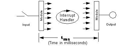
In the area of interrupt processing, performance is measured from the time the input signal arrives at the input module, to the time an output point change state, and everything in between. This takes into consideration I/O module latency times, controller overhead for servicing interrupts and the size of the interrupt handler, as is depicted in the diagram below.
This illustration shows the general performance capabilities of the unit.
The overall performance range of the Quantum system, measured in milliseconds, is shown in the table below:
|
Processor
|
Interrupt Type
|
1 ms Throughput
|
2 ms Throughput
|
Logic within the Interrupt Handler
|
I/O Module
|
|
CPU
|
Hardware
|
2 Interrupts
|
4 Interrupts
|
Increment Counter
|
In:HLI340000
Out:DDO35300
|

