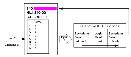
This mode latches input signals, but does not cause an interrupt to be generated within the Quantum controller. A latched signal is guaranteed to be read by the module. Immediately after the reading process, the controller automatically unlatches the input state. This is normally used in applications where the input signal on-time is less than the controllers module service time, meaning the controller could miss the input signal. Data from latch inputs is serviced using the normal input update methods, at the end of the scan (no user intervention is required).
Automatic Latch/Unlatch Method
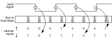
When an input point is configured for latch mode falling edge, the corresponding input data will be latched on the transition of 24 Vdc to 0. The data will be presented to the controller as logical zero. The corresponding input data for this point will be cleared to a one’ s state at the end of that respective scan (see below and following illustration).
When an input point is configured for latch mode rising edge, the corresponding input data will be latched on the transition of 0 to 24 Vdc. The data will be presented to the controller as logical one. The corresponding input data for this point will be cleared to a zero’ s state at the end of that respective scan (see below and following illustration).
The following illustration shows the relationship between the input and the end of scan read. The input signal is connected to two inputs configured for Latch mode, one for rising edge and one for falling edge.
NOTE: If the module is configured in a split mode, where there are interrupts and latched inputs, note that the latched input data is read and cleared at the interrupt service time and may not be valid at the end of the scan.
The following illustration shows details of the automatic latch/unlatch method.

