Quantum EIO System Components
A ring design establishes cable redundancy, without the need to run dual cables. The following figure shows a basic daisy chain ring architecture of a Quantum EIO Hot Standby system:
1A+2A
CPU and copro of primary controller
1B+2B
CPU and copro standby controller
3
CPU-sync fiber optic link
4A+4B
primary and standby power supplies
5A+5B
primary and standby remote I/O head modules
6
Ethernet connection between remote I/O head modules
7
Ethernet remote I/O drops in a daisy chain loop configuration
8
Control Expert workstation
NOTE: The architectures described in this document have been tested and validated in various scenarios. If you intend to use architectures different than the ones described in this document, test and validate them thoroughly before implementing.
The 140CRP31200 remote I/O head module is connected to the 140CRA31200 or BMX CRA 312 •0 remote I/O adapter modules through Ethernet cables and, if necessary, dual-ring switches (). This network uses a daisy chain ring topology and the RSTP 2004 protocol.
Up to 30 remote I/O drops can be connected to the two 140CRP31200 modules in a simple daisy chain loop. If you want 31 drops, use a high-capacity daisy chain loop topology and refer to the Quantum EIO System Planning Guide for further details.
The other side of the main ring has the two 140CRP31200 modules directly connected without remote I/O drops between them. There can be a maximum of 2 DRSs on this side of the ring.
The minimum Quantum Hot Standby system does not require any remote I/O drops, but it includes at least one pair of 140CRP31200 remote I/O head modules.
The parts list for a Quantum EIO Hot Standby system is as follows:
|
Name
|
Reference
|
Minimum Firmware Version
|
Number of Units
|
|
Quantum standard racks
|
140 XBP 0•• 00
|
—
|
2
|
|
Quantum power supplies
|
140 CPS ••• •0
|
—
|
2
|
|
Quantum Hot Standby controller1
|
140 CPU 671 60
140 CPU 672 60
140 CPU 672 61
|
3.0
3.0
3.0
|
2
|
|
Quantum Hot Standby remote I/O head modules1
|
140CRP31200
|
1.0
|
2
|
|
Quantum Hot Standby remote I/O drop modules
|
140CRA31200
BMX CRA 312 •01
|
1.0
|
As needed
|
|
dual-ring switch (DRS)
|
TCSESM083F23F1
TCSESM063F2CU1
TCSESM063F2CS1
|
6.0
|
As needed
|
|
Quantum Hot Standby distributed I/O head modules
|
140NOC78000
|
1.0
|
As needed (8 maximum)
|
|
Quantum Hot Standby control head modules
|
140NOC78100
|
1.0
|
As needed (2 maximum)
|
1A BMX CRA 312 •0 remote I/O adapter module requires that the:
NOTE: When used in a Hot Standby configuration, Ethernet backplanes and their associated plugged modules behave in the same manner as in a standalone system, which means there is no bump or loss of I/O control during a switchover.
NOTE: The preceding hardware is required in Hot Standby systems, but it does not provide a useful redundant system because no redundantly managed I/O modules are included.
NOTE:
-
For more information about the remote I/O head modules, refer to the Quantum EIO Remote I/O Modules Installation and Configuration Guide.
-
For more information about the distributed I/O head modules, refer to the Quantum EIO Distributed I/O Network Installation and Configuration Guide.
-
For more information about the control head modules, refer to the Quantum EIO Control Network Installation and Configuration Guide.
Additional Quantum EIO Redundancy
A Quantum EIO Hot Standby system has inherent cable redundancy because of the daisy chain loop design.
In this configuration there are
3 links between the primary and standby PLCs:
-
directly between the 2 copros over the
sync-link
-
over the daisy-chained Ethernet remote I/O drops between the two 140CRP31200 remoe I/O head modules
-
over the Ethernet direct link between the two 140CRP31200 remote I/O head modules
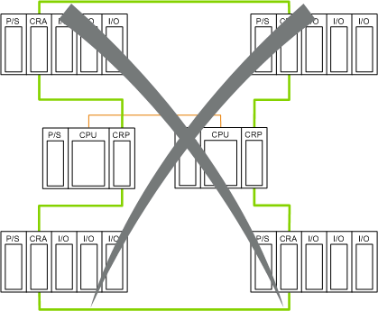
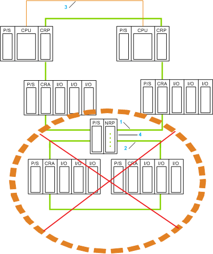
This direct link cannot have remote or distributed I/O drops. For example, the following is not allowed:
Just as in a standalone system, a can be used in a Hot Standby system to:
-
insert a sub-ring into the main daisy chain ring
-
isolate the sub-rings from each other and from the main ring to improve system performance
-
enable recovery support for devices and cables on the sub-rings
-
enable the use of fiber cable for distances greater than 100 m between 2 contiguous remote devices
-
enable distributed I/O devices to participate on the remote I/O network
NOTE: A DRS predefined configuration,
C15, is available for Hot Standby systems that enables you to separate the primary and standby PLCs by a long distance using fiber optic cable.
NOTE: You can also use a BMX NRP 020• fiber converter module to convert copper cable to fiber cable for distances greater than 100 m. For more details, refer to the
fiber converter module topic.
NOTE: Schneider Electric provides predefined configuration files to configure DRSs on Quantum Ethernet I/O main rings and sub-rings. For more information, refer to the Predefined Configuration Files chapter in the Quantum EIO System Planning Guide.
For your performance calculations (i.e., maintaining a 50 ms communication recovery time), count each DRS as 2 Ethernet devices. Refer to the Quantum EIO System Planning Guide for details on performance calculations and DRS capabilities.
Dual-Ring Switch (DRS) Topology Examples
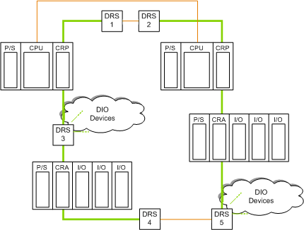
The following example shows 2 possible uses of DRSs:
Actions of the DRSs:
1 & 2
These DRSs connect the two 140CRP31200 remote I/O head modules in the Hot Standby PLCs using fiber optic cable separated by a distance > 100 m (long-haul).
3
This DRS attaches distributed I/O devices to the main daisy chain ring.
4 & 5
These DRSs connect the 140CRA31200 or BMX CRA 312 •0 remote I/O adapter modules of 2 remote I/O drops using fiber optic cable because the distance is > 100 m.
5
This DRS also attaches distributed I/O devices to the main daisy chain ring.
On this ring there are two 140CRP31200 devices, two 140CRA31200 or BMX CRA 312 •0 devices and 5 DRSs that count as 10 devices for a total of 14 devices. 32 - 14 = 18 additional devices can be added to this ring.
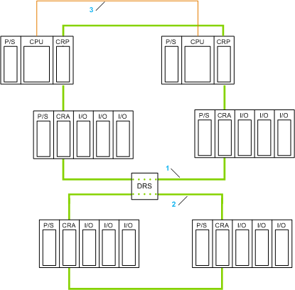
A DRS can be used to connect a sub-ring to the main ring:
1
main ring
2
sub-ring
3
CPU-sync fiber optic link, using fiber optic cable
A single 140CRP31200 device can support up to 31 remote I/O drops. The main ring can support a maximum of 32 devices — including 140CRP31200 modules, 140CRA31200 or BMX CRA 312 •0 modules, and DRSs — and provide a maximum recovery time of 50 ms.
NOTE:
-
The recovery time of 50 ms applies to remote I/O, which is deterministic, and not to distributed I/O, which is not deterministic.
-
When counting the number of devices in a ring, for the purpose of determining recovery time, each DRS counts as 2 devices.
In the previous sample network, the main ring has 6 devices for recovery time calculations:
-
140CRP31200 remote I/O head module: 2 devices
-
140CRA31200 or BMX CRA 312 •0 remote I/O adapter module: 2 devices
-
DRSs: the single DRS counts as 2 devices
Therefore, 32 – 6 = 26 additional devices can be added to the main ring.
Refer to the Quantum EIO System Planning Guide for details on the sub-ring topologies and design rules.
The BMX NRP 020• fiber converter module is an alternative method to using a to provide fiber optic communications in a Quantum EIO Hot Standby system.
You can install BMX NRP 020• fiber converter modules on M340 racks and M340 Ethernet remote I/O drops to:
-
extend the total length of the Quantum EIO network — when you have Ethernet remote I/O drops in separate areas of a factory that are more than 100 m apart
-
improve noise immunity
-
resolve grounding issues — when using different grounding methods is required between 2 buildings
You can use BMX NRP 020• fiber converter modules in a long-haul link to extend the distance between the 2 PLCs beyond 100 m. Use BMX NRP 020• modules to connect to in a
high-capacity daisy chain loop system when you wish to have Ethernet remote I/O or distributed I/O or .
NOTE: Connect the fiber and copper cable to the correct ports on the BMX NRP 020• module. Refer to the BMX NRP 020• M340 NRP Module User Guide for details.
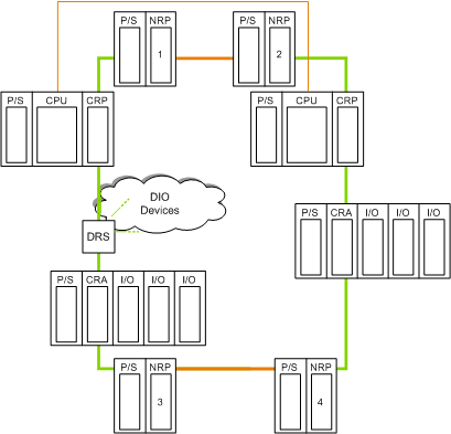
1 & 2
These two BMX NRP 020• fiber converter modules connect the two 140CRP31200 remote I/O head modules in the 2 Hot Standby PLCs that are separated by a distance > 100 m (long-haul), using fiber optic cable.
3 & 4
These two BMX NRP 020• fiber converter modules connect the 140CRA31200 or BMX CRA 312 •0 remote I/O adapter modules in the 2 Ethernet remote I/O drops that are separated by a distance > 100 m, using fiber optic cable.
To install NRP modules in a Quantum EIO system to extend the distance between 2 PLCs in a long-haul Hot Standby link beyond 100 m, follow these steps:
|
Step
|
Action
|
|
1
|
Install a BMX NRP 020• fiber converter module on an M340 rack for both Hot Standby PLCs.
|
|
2
|
Connect the fiber transceiver ports of the BMX NRP 020• modules on the two M340 racks to each other, using fiber cable.
-
Use BMX NRP 0200 modules to support multi-mode fiber if the distance between them is less than 2 km.
-
Use BMX NRP 0201 modules to support single-mode fiber if the distance between them is between 2 km and 15 km.
|
|
3
|
Connect the copper port of the BMX NRP 020• module to the 140CRP31200 remote I/O head module on both local racks, using copper cable.
|
NOTE: You can install BMX NRP 020• modules on the main ring and subrings for copper-to-fiber transitions. However, you cannot use these modules to connect sub-rings to the main ring.
1
main ring
2
sub-ring
3
CPU-sync fiber optic link
4
BMX NRP 020• fiber converter module 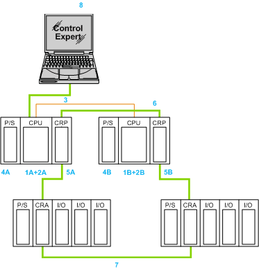
 WARNING