S908 Hot Standby Hardware and Topology
Original instructions
S908 System Components
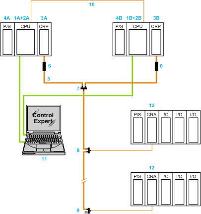
A basic, one-bus architecture of an S908 Quantum Hot Standby system:
1A+2A 
CPU and copro of Primary controller
1B+2B 
CPU and copro of Standby controller
3A+3B 
Quantum RIO head modules
4A+4B 
Primary and Standby power supplies
5          
Coaxial cable
6         
 Self-terminating F adapter
7          
Splitter
8          
Tap
9          
 Tap with Trunk terminator
10        
CPU-Sync fiber optic link
11        
Control Expert workstation
12        
S908 RIO Drops
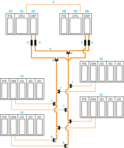
A 2-bus architecture S908 system:
1A  
CPU of Primary controller
1B  
CPU of Standby controller
2A+2B 
Quantum RIO Head modules
3A+3B 
Primary and Standby power supplies
4          
Coaxial cable
5         
 Self terminating F adapter
6          
Splitter
7          
Tap
8         
 Tap with Trunk terminator
9          
CPU-Sync fiber optic link
10        
S908 RIO Drops
NOTE:
In a 2-bus architecture:
  • Separate cable runs are required to achieve redundancy. In a one-bus architecture, a single cable break causes the loss of communication to RIO beyond the point of the break.
  • When implementing a 2-bus architecture, place each bus in a separate channel, and separate the channels by some distance. In this way, a single event is less likely to damage both cables.
S908 RIO Network
Dual cabling offers cable redundancy as well as CPU redundancy in an S908 hot standby architecture.
There can be up to 31 RIO drops connected to the two RIO Head modules.
The minimum Quantum Hot Standby does not require any RIO drops, but it must include at least one pair of connected RIO Head modules.
Parts List
The parts list for a S908 single-cabled Hot Standby system is as follows:
Name
Reference
Minimum Firmware Version
Number of Units
Quantum Standard Racks
140 XBP 0•• 00
2
Quantum Power Supplies
140 CPS ••• •0
2
Quantum Hot Standby Controller
140 CPU 672 61
140 CPU 671 60
140 CPU 672 60
140 CPU 671 60S
140 CPU 678 61
140 CPU 678 61C
2
2
2
2
2
2
Quantum Hot Standby RIO Head Modules
140 CRP 931 00
140 CRP 932 00
2.0
2.0
2
2
Quantum Hot Standby RIO Drop Modules
140 CRA 931 00
140 CRA 932 00
As needed
As needed
Self Terminating F Adaptor
52 0411 000
2
Splitter
MA 0186 100
1
Tap
MA 0185 100
As needed
Trunk Terminator
52 0422 000
As needed
NOTE: The above hardware is always required in Hot Standby systems, but it does not provide a useful redundant system because no redundantly managed I/O modules are included.
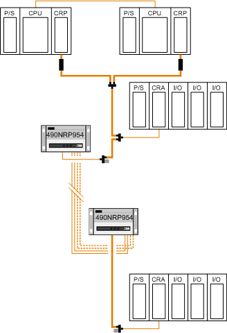
490 NRP 954 00 Fiber Optic Repeaters
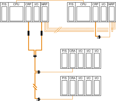
490 NRP 954 00 repeaters are only used between S908 CRP RIO Drop modules:
For help in calculating the maximum length of the optical path between two 490 NRP 954 00 fiber optic repeaters, refer to the Modicon 40 NRP 954 00 and 140 NRP 954 01C Fiber Optic Repeaters User Guide.
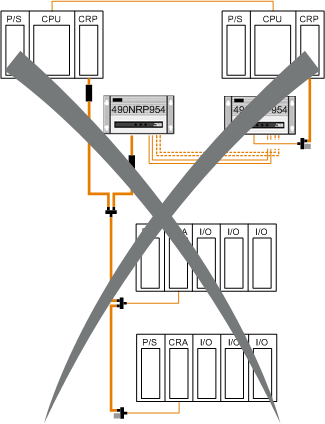
The sync-link between the CRP modules in the primary and standby main racks must be an uninterrupted point-to-point connection. You cannot use 490 NRP 954 00 repeaters between the two Hot Standby CRP RIO Drop modules:
WARNING
UNINTENDED EQUIPMENT OPERATION
  • Make an uninterrupted point-to-point connection between the Hot Standby CPU-sync link ports.
  • Do not connect any other Ethernet devices on the same network cabling as the CPU-sync link.
  • Do not exceed maximum Ethernet cable lengths for the type of cable selected.
Failure to follow these instructions can result in death, serious injury, or equipment damage.
140 NRP 954 0• Fiber Optic Repeaters
140 NRP 954 0• repeaters can be used between S908 CRP RIO Drop modules:
140 NRP 954 0• repeaters can be used between the two Hot Standby CRP RIO Drop modules: