Two Controllers: Primary and Standby
The basic requirement for a Quantum Hot Standby system is to use two identical Hot Standby PLCs of one of the following types:
These controllers must have the same firmware versions and be positioned in the same slot assignments for all modules in their respective Quantum racks. They must also run the same application program.
In a system that is operating with both controllers fully functional, the two identical controllers assume one of two operating modes:
-
One controller acts as the Primary PLC, operating in the “Run Primary” mode.
-
The other controller acts as the Standby PLC, operating in the “Run Standby” mode.
The role of the Primary PLC is almost identical to that of a standalone PLC. It runs your entire application program and provides the normal control functions you would expect from a standalone PLC.
The Primary CPU:
The major differences of the Primary CPU from a standalone PLC are:
-
The Primary Hot Standby controller communicates regularly with its Standby PLC so that the Standby remains ready to assume the Primary role if required.
-
The Primary PLC monitors itself and certain associated equipment for specific conditions that dictate a switchover.
The role of the Standby PLC is different from a standalone PLC. Its role is to remain ready to assume control of the system at a moment's notice and yet not interfere with the control asserted by the Primary controller. To do so, it must regularly receive application data and the current status of the remote and distributed I/O from the Primary controller.
The Standby CPU:
-
executes only the first section of the application program MAST task
-
verifies the availability of the Primary CPU and CRP modules
-
can update the Primary CPU about the status of its CPU, CRP modules and drop connections
-
controls only its local I/O, not the remote or distributed I/O
The Standby PLC also regularly communicates information back to the Primary PLC using a group of system words: the reverse transfer registers. The content of these system words is programed (and modified) in the first section of the user application running in the standby CPU.
The most common use is to provide the Primary PLC information about the health of the Standby PLC and its associated modules.
Distinguishing Between Controllers
The two physical controllers are assigned as either PLC A or PLC B. This assignment is used to configure the IP address of the Ethernet CRP RIO Head modules.
Distinguishing between the A and B Hot Standby CPUs allows:
Never assume that a PLC is in a certain operating mode before installing, operating, modifying, or servicing it. The operating modes of both Hot Standby PLCs can be determined by viewing their LCD keypads, LEDs and System Status Words.
NOTE: In a Quantum Ethernet I/O Hot Standby system, the Ethernet CRP IP addresses are not swapped during a switchover.
At the first startup of a CPU without the A/B assignment the Hot Standby menu is displayed on the keypad LCD allowing the user to assign A or B to the CPU.
You can also assign/change the A/B assignment of the Hot Standby CPUs using the keypad LCD. After modification the CPUs reset its CRP RIO Head modules.
NOTE: When a CPU is in the RUN mode its A/B assignment cannot be changed. It must be in the STOP mode to change its assignment.
The two CPUs cannot have the same A or B assignment:
-
If a CPU starts with the same assignment as the other CPU, this CPU goes to the STOP mode, displays the Hot Standby menu and waits for an assignment from the keypad.
-
If you replace one of the PLCs, the identification of PLC A and PLC B may no longer align with the primary and standby operating modes.
The same thing is true for any physical labels you might apply to your PLCs to distinguish them in your system.
Ethernet CRP Head module IP addresses are based on the user configured IP address in Control Expert and the A/B assignment.
Establishing the Primary and Standby Controllers
If the system is properly configured, the first Hot Standby PLC to which power is applied assumes the role of the Primary controller. Therefore, you can determine controller roles by delaying the application of power to one PLC using a time-lag relay or some related means.
When you apply power simultaneously to two properly configured Hot Standby PLCs, the firmware automatically assigns the primary role to the A CPU.
NOTE: This assignment can be changed using the CPU
keypad
Identical RIO Head Modules Required
In addition to requiring two identical controllers, a Quantum Hot Standby system requires a minimum of two identical Quantum RIO “head” modules, one on each rack.
These two modules can be:
-
140 CRP 931 00 (for S908 I/O drops)
-
140 CRP 932 00 (for S908 I/O drops)
-
140CRP31200 (for Quantum Ethernet I/O Ethernet I/O Drops)
The rack positions and firmware versions of the CRP modules must be identical in the main racks of the Primary and the Standby systems.
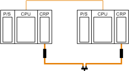
The CPU-sync link is the physical communications for providing Quantum Hot Standby redundancy. It is located between the Hot Standby (labeled “HSBY Link”) ports on the face of each controller. Do not include switches and hubs on this link. Refer to
Hot Standby Sync-Link for details.
A RIO network (S908 and/or Ethernet) is used as a redundant link for the Hot Standby system. This redundant link is mandatory for some operating modes and error detection.
Either an S908 and/or Ethernet RIO CRP head module can be used for the RIO redundant link.
If you are not using remote I/O in a Hot Standby system, you must still install S908 or Ethernet CRP Head modules and their connecting network.
S908 system without any remote I/O drops:
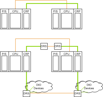
Ethernet systems without remote I/O:
In addition to the
CPU Sync-Link, an Ethernet system has two types of connections between the CRPs that can use ConneXium extended managed switches, called dual ring switches (DRSs) in this architecture:


 WARNING