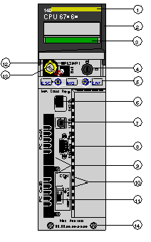
The figure shows a Hot StandBy CPU module front panel:
1
Model number, module description, color code
2
Lens cover (open)
3
LCD display (here covered by lens cover)
4
Key switch
5
Keypad (with 2 red LED indicators)
6
Modbus port (RS-232) (RS-485)
7
USB port
8
Modbus Plus port
9
PCMCIA slots A and B
10
LED indicators (yellow) for Ethernet communication
11
HSBY Link (sync-link) fiber optic communication port
12
Reset button
13
Battery (user installed)
14
2 screws
NOTE: Quantum CPUs are equipped with two receptacles for Schneider PCMCIA cards (other cards are not accepted).
