|
Configuring IP Address Settings
|
|
|
Original instructions
|
|
Step
|
Action
|
|
|---|---|---|
|
1
|
In the DTM Browser, right-click the M580 CPU.
|
|
|
2
|
Select Open from the context menu.
Result: The master DTM configuration window opens.
|
|
|
3
|
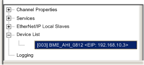
Use the tree control on the left side of the DTM configuration window to navigate to a HART analog I/O module that you previously added to the configuration:
 |
|
|
4
|
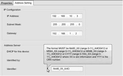
Select the Address Setting tab to access the IP address configuration settings:
 |
|
|
5
|
Use the following fields to configure IP address settings for the selected HART analog I/O module:
|
|
|
IP Address
|
Enter the IP address that the FDR server in the CPU serves to the selected HART analog I/O module.
|
|
|
Subnet Mask:
|
Accept the default value.
|
|
|
Gateway:
|
Accept the default value.
|
|
|
DHCP for this device
|
Select Enabled.
|
|
|
Identified by
|
Select Device Name.
|
|
|
Identifier
|
Enter the Device Name identifier for the selected HART analog I/O module.
NOTE: Refer to the following topic: Creating a Device Name for DHCP. |
|
|
6
|
Click Apply.
|
|
|
7
|
In the CPU master DTM, select Channel Properties in the navigation tree.
|
|
|
8
|
Confirm that the Source IP Address is correct.
NOTE: Control Expert uses this IP address to communicate with the CPU. |
|
|
Parameter
|
Description
|
|---|---|
|
Rack ID
|
A 4-character field that identifies the rack used for the module:
|
|
Slot Number
|
A field that identifies the position of the module in the rack.
|
|
Device Name
|
Use the following module names for the purpose of generating a Device Name:
|