|
|
Original instructions
|
  DANGER DANGER |
|
HAZARD OF ELECTRICAL SHOCK, EXPLOSION OR ARC FLASH
Terminal block must be connected or disconnected with sensor and pre-actuator voltage switched off.
Failure to follow these instructions will result in death or serious injury.
|
 CAUTION CAUTION |
|
EQUIPMENT DAMAGE
Do not plug an AC terminal block into a DC module. This will cause damage to the module.
Failure to follow these instructions can result in injury or equipment damage.
|

|
Step
|
Action
|
|---|---|
|
1
|
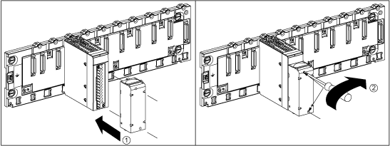
Once the module is in place on the rack, install the terminal block by inserting the terminal block encoder (the rear lower part of the terminal) into the module's encoder (the front lower part of the module), as shown above.
NOTE: The module connector have indicators which show the proper direction to use for terminal block installation. |
|
2
|
Fix the terminal block to the module by tightening the 2 mounting screws located on the lower and upper parts of the terminal block.
Tightening torque: 0.4 N•m (0.30 lbf-ft).
|
 WARNING WARNING |
|
UNEXPECTED BEHAVIOUR OF APPLICATION
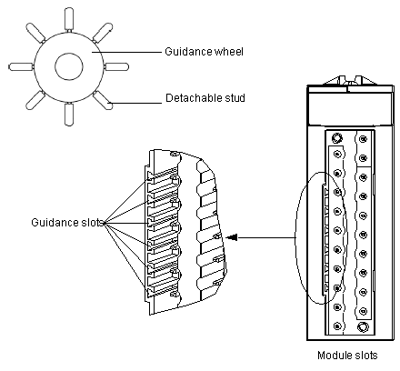
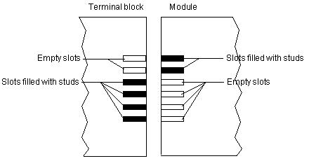
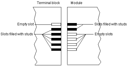
Code the terminal block as described below to prevent the terminal block from being mounted on another module.
Plugging the wrong connector could cause unexpected behaviour of the application.
Failure to follow these instructions can result in death, serious injury, or equipment damage.
|
 CAUTION CAUTION |
|
DESTRUCTION OF THE MODULE
Code the terminal block as described below to prevent the terminal block from being mounted on another module.
Plugging the wrong connector could cause the module to be destroyed.
Failure to follow these instructions can result in injury or equipment damage.
|


