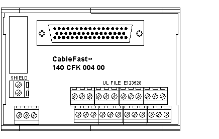
The K block is used for analog outputs. This interface provides plus, minus, shield, and power supply interface for both field and loop power configurations.
The following figure shows the 140CFK00400 terminal block.
The following are the application notes for the 140CFK00400 module.
-
Configuration – Four analog outputs with a common loop supply. Each point is allocated four terminals.
-
Compatibility – This terminal block provides four individually unfused connection point sets for the 140ACO02000 and 140AVO02000 analog output modules.
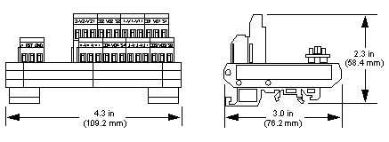
The following figures show the dimensions for the 140CFK00400 module.
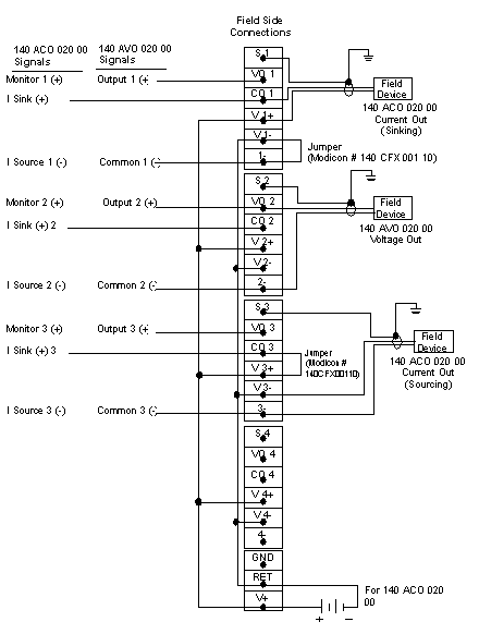
Wiring Diagram (Source Grounding)
The following shows the wiring for the 140CFK00400 (source grounding) module.
NOTE:
-
When used with the 140AVO02000 analog voltage out module, the master override connections and range select must be made on the Quantum I/O connector.
-
When using a single power supply, there will be no channel-to-channel isolation of input points.
-
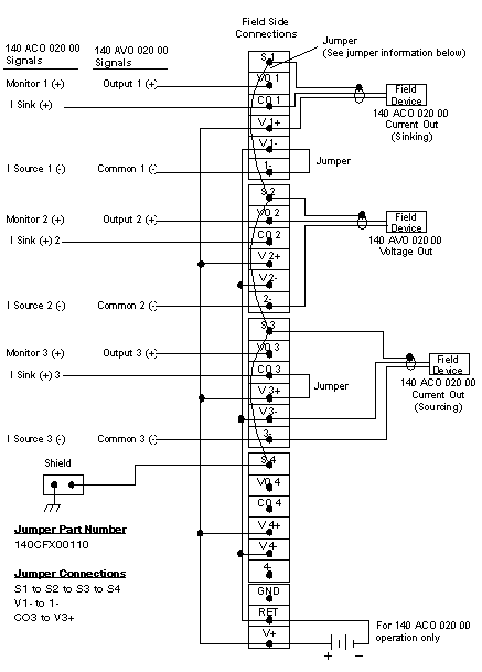
For the required jumper options for the 140ACO02000, see wiring diagram in
ACO02000 I/O Module.
-
The GND (ground) terminal point is not connected.
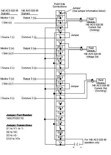
Wiring Diagram (Instrument Grounding)
The following figure shows the wiring for the 140CFK00400 (instrument grounding) module.
NOTE:
-
When used with the 140AVO02000 analog voltage out module, the master override connections and range select must be made on the Quantum I/O connector.
-
When using a single power supply, there will be no channel-to-channel isolation of input points.
-
-
The GND (ground) terminal point is not connected.
Wiring Diagram (Chassis Grounding)
The following shows the wiring for the 140CFK00400 (chassis grounding) module.
NOTE:
-
When used with the 140AVO02000 analog voltage out module, the master override connections and range select must be made on the Quantum I/O connector.
-
When using a single power supply, there will be no channel-to-channel isolation of input points.
-
-
The GND (ground) terminal point is not connected.
