|
General Information
|
|
|
Original instructions
|

|
Power ratings
|
150 VAC/VDC @ 0.5 A/point
|
|
|
150 VAC/VDC @ 2.0 A/point *
|
||
|
* Requires the 140 CFG 016 00 terminal block and the 140 XTS 012 •• cable
|
||
|
Dielectric withstanding voltage
|
1060 VAC and 1500 VDC
|
|
|
Creepage and clearance
|
per IEC 1131, UL 508, CSA 22.2 #142-1987
|
|
|
Terminal block wire size/terminal
|
One wire
|
2.5 mm2 (12 AWG)
|
|
Two wires)
|
1.0 mm2 (6 AWG) and above (See below for the maximum number of wires allowed per terminal.
|
|
|
Note: It is recommended that no more than two wires be used at one time.
|
||
|
Wire Size
|
Number of Wires
|
|
|
#24
|
4
|
|
|
#22
|
4
|
|
|
#18
|
3
|
|
|
#16
|
2
|
|
|
#14
|
1
|
|
|
#12
|
1
|
|
|
Terminal screw
|
size
|
M3
|
|
screwdriver head size
|
3.3 mm (0.13 in) flat head min.
|
|
|
screw type
|
Captive
|
|
|
screw finish
|
Tin plate (197 micro in min.)
|
|
|
torque
|
0.8 Nm (7.2 lb-in)
|
|
|
System flammability rating
|
94 V-2
|
|
|
Temperature
|
Operating
|
0 ... 60 °C (32 ... 140 °F)
|
|
Storage
|
-40 ... +65 °C (-40 ... +149 °F)
|
|
|
Humidity
|
0 ... 95% RH noncondensing
|
|
|
Altitude
|
6,666 ft. (2000 m) full operation
|
|
|
Shock
|
+/-15 g peak, 11 ms, half sine wave
|
|
|
Vibration
|
10 ... 57 Hz @ 0.075 mm displacement
|
|
|
57 ... 150 Hz @ 1 g, total 10 sweeps
|
||
|
Mounting configuration
|
DIN rail mount, NS35/7.5 and NS32
|
|
|
140 CFA 040 00
|
140 CFB 032 00
|
140 CFC 032 00
|
140 CFD 004 00
|
140 CFE 032 00
|
140 CFG 016 00
|
140 CFH 008 00
|
140 CFI 008 00
|
140 CFJ 004 00
|
140 CFK 004 00
|
|
|---|---|---|---|---|---|---|---|---|---|---|
|
140 ACI 030 00
|
X
|
X
|
X
|
|||||||
|
140 ACO 020 00
|
X
|
X
|
X
|
|||||||
|
140 ACI 040 00
|
X
|
|||||||||
|
140 ACO 130 00
|
X
|
|||||||||
|
140 ARI 030 10
|
X
|
|||||||||
|
140 ATI 030 00
|
X (see note 3)
|
|||||||||
|
140 AMM 090 00
|
X
|
|||||||||
|
14 AVI 030 00
|
X
|
X
|
X
|
|||||||
|
140 AVO 020 00
|
X
|
X
|
||||||||
|
140 DAI 340 00
|
X
|
X
|
||||||||
|
140 DAI 353 00
|
X
|
X
|
X
|
X
|
||||||
|
140 DAI 440 00
|
X
|
X
|
||||||||
|
140 DAI 453 00
|
X
|
X
|
X
|
X
|
||||||
|
140 DAI 540 00
|
X
|
X
|
||||||||
|
140 DAI 543 00
|
X
|
|||||||||
|
140 DAI 553 00
|
X
|
X
|
X
|
X
|
||||||
|
140 DAI 740 00
|
CableFast not allowed
|
|||||||||
|
140 DAI 753 00
|
||||||||||
|
140 DAM 590 00
|
X see note 1
|
|||||||||
|
140 DAO 840 00
|
–
|
X (see note 2
|
||||||||
|
140 DAO 840 10
|
X (see note 2
|
|||||||||
|
140 DAO 842 10
|
–
|
X (see note 2
|
||||||||
|
140 DAO 842 20
|
–
|
X (see note 2
|
||||||||
|
140 DAO 853 00
|
X see note 1
|
|||||||||
|
140 DDI 153 10
|
X
|
X
|
||||||||
|
140 DDI 364 00
|
not compatible with cable fast. See in the related chapter of the I/O reference guide for recommended cables
|
|||||||||
|
140 DDI 353 00
|
X
|
X
|
X
|
|||||||
|
140 DDI 353 10
|
X
|
|||||||||
|
140 DDI 673 00
|
X
|
|||||||||
|
140 DDI 841 00
|
X
|
|||||||||
|
140 DDI 853 00
|
X
|
X
|
X
|
X
|
||||||
|
140 DDM 390 00
|
X
|
|||||||||
|
140 DDM 690 00
|
X see note 1
|
|||||||||
|
140 DDO 153 10
|
X
|
|||||||||
|
140 DDO 353 00
|
X
|
X
|
X
|
|||||||
|
140 DDO 353 01
|
X
|
X
|
X
|
|||||||
|
140 DDO 353 10
|
X
|
|||||||||
|
140 DDO 364 00
|
not compatible with cable fast. See in the related chapter of the I/O reference guide for recommended cables
|
|||||||||
|
140 DDO 843 00
|
X see note 2
|
|||||||||
|
140 DDO 885 00
|
X see note 1
|
|||||||||
|
140 DRA 840 00
|
X see note 1
|
|||||||||
|
140 DRC 830 00
|
X see note 1
|
|||||||||
|
140 DSI 353 00
|
X
|
|||||||||
|
140 DVO 853 00
|
X
|
|||||||||
|
140 SAI 940 00S
|
not compatible with cable fast.
|
|||||||||
|
140 SDI 953 00S
|
X
|
|||||||||
|
140 SDO 953 00S
|
X
|
|||||||||
|
X = Valid Selections.
|
||||||||||
|
Block Number
|
Block Description
|
|---|---|
|
140 CFA 040 00
|
The A block is a straight through point to point connection on the terminal block. Wiring of this block is identical to wiring the Quantum I/O connector (140 XTS 002 00).
|
|
140 CFB 032 00
|
The B block is used for individually fused 2-wire digital inputs. This terminal block is designed to help prevent a single point error from affecting the remaining inputs. It is not recommended for 1-wire inputs powered from the field.
|
|
140 CFC 032 00
|
The C block provides connection for 32 group fused input or output points. The block may be used for 1- or 2-wire inputs or outputs, and features a fuse per group, four groups total. Users select input or output mode via four switches located on the module. (The default is input mode.)
|
|
140 CFD 032 00
|
The D block is used for sensors requiring either 2- or 3-wire electrical interface. A fuse per group is supplied to accommodate the I/O module (4) groups.
|
|
140 CFE 032 00
|
The E block provides connection for 32 individually fused 24 VDC outputs. 1- and 2-wire interfacing may be selected. Field power must be supplied to the four groups.
|
|
140 CFG 016 00
|
The G block is a high power output block used on both AC and DC circuits requiring up to 2 A. Individual fusing is provided and may be used in both 1- and 2-wire installations. It is also used for isolated AC modules.
|
|
140 CFH 008 00
|
The H block is used for analog inputs, with individual fusing provided per channel. This interface provides plus, minus, shield, and power supply interface for both field and loop power configurations.
|
|
140 CFI 008 00
|
The I block is used for analog inputs. This interface provides plus, minus, shield, and power supply interface for both field and loop power configurations.
|
|
140 CFJ 004 00
|
The J block is used for analog outputs, with individual fusing provided per channel. This interface provides plus, minus, shield, and power supply interface for both field and loop power configurations.
|
|
140 CFK 004 00
|
The K block is used for analog outputs. This interface provides plus, minus, shield, and power supply interface for both field and loop power configurations.
|


|
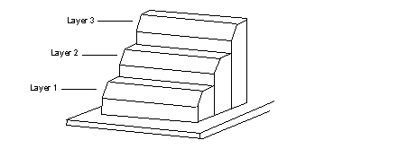
Signal
|
Layer 3
|
||
|
Positive
|
Signal
|
Signal
|
Layer 2
|
|
Negative
|
Positive
|
Negative
|
Layer 1
|