Modicon Quantum Ethernet Modules Overview
Original instructions
Overview
The following information provides overviews of all Modicon Quantum Ethernet modules.
General Description
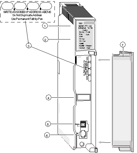
The Modicon Quantum Ethernet module, shown below, is one of the latest models in a line of Modicon Quantum Ethernet TCP/IP modules designed to make it possible for a Modicon Quantum PLC to communicate with devices over an Ethernet network. The electronics for the Ethernet modules are contained in a standard Modicon Quantum single-width case that takes up one slot in a Modicon Quantum backplane. The module, which is capable of being hot swapped, can be plugged into any available slot in the backplane.
The NOE 771 x0 and NOE 771 x1 modules provide real-time peer-to-peer communications and I/O scanning and a Modbus/TCP server. The included HTTP services provide maintenance and configuration utilities to the module.
Front View
The following figure shows the front of the NOE 771 00 Ethernet module as an example for all Ethernet modules.
1 
model number, module description, color code
2 
LED display
3 
IP Address writable area
4 
Global address label
5 
100 BASE-FX MT-RJ cable connector
6 
10/100 BASE-T RJ45 cable connector
7 
removable door
Key Ethernet Services
The key Ethernet services of the 140 NOE 771 (-00, -01, -10, -11) and 140 NWM 100 00 models are listed below:
Service
-00
-01
-10
-11
NWM
X
X
X
X
X
X
X
X
X
X
X
X
X
X
X
X
X
X
X
X
X
X
X
X
X
X
X
X
X
X
X
X
X
X
X
X
X
Hot Standby
X
X
X
X
X
X
X
X
X
X
X
X
X
X
X
X
X
User-programmed Web pages
X
X
X
JAVA Virtual Machine
X
Fiber optic connection
X
X
X
X
RJ45 connection
X
X
X
X
X
X
X
NOTE: In the detailed description of the key features, only modules in the NOE family are named. The features are also available for the 140 NWM 100 00 module, depending on the listed properties in the above table.
NOTE: In Control Expert software, the 140 NWM 100 00 module is set in the TCP/IP Regular Network family, although it belongs to the TCP/IP FactoryCast network family. So, the services listed above (I/O scanning, Global Data, address server, Bandwidth monitoring) are not supported by the module. However, they can be selected in the TCP/IP regular network configuration in Control Expert. (Even if they are configured, those services won't work with the module.)
Maximum Number of Networks Per CPU
The following table summarizes the maximum number of networks per CPU, where "networks" means the sum of NOE, Modbus+ and any other communication modules:
Modicon Quantum CPU Type
Supported Number of Networks
140 CPU 311 10
2
140 CPU 434 12A
6
140 CPU 534 14A
6
140 CPU 651 50
6
140 CPU 651 50
6
140 CPU 652 60
6
140 CPU 658 60
6
140 CPU 670 60
3
140 CPU 671 60
6
140 CPU 672 60
6
140 CPU 672 61
6
140 CPU 678 61
6
Front Panel Components
The front panel of the Ethernet modules contains identification markings, color codes, and LED displays. A writable area for an IP address, a global address label, and two Ethernet cable connectors is located behind the removable front panel door.
The following table provides a description of the front panel components that are shown in following figure:
Component
Description
Indicates the operating status of the module, and the fiber optic or Ethernet communications network to which it is connected.
IP Address Area
Provides a writable area to record the module’s assigned IP address.
Global Address Label
Indicates the module’s global Ethernet MAC address assigned at the factory.
100 BASE-FX Connector
Provides an MT-RJ socket for connection to a 100-megabit fiber-optic Ethernet cable.
10/100 BASE-T Connector
Provides an RJ45 socket for connection to a shielded, twisted pair Ethernet cable.