|
Building and Downloading the Configuration Program
|
|
|
Original instructions
|
|
Step
|
Action
|
|---|---|
|
1
|
Ensure that the Quantum system is powered up.
|
|
2
|
Connect the PLC to the PC with a USB cable.
|
|
3
|
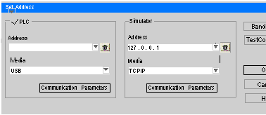
On the PC, click the Control Expert PLC\Set Address tab to bring up the Set Address dialog box.
 |
|
4
|
Select USB in the PLC Media box.
|
|
5
|
Leave the PLC Address field blank.
|
|
6
|
Click OK.
|
|
7
|
|
Step
|
Action
|
|---|---|
|
1
|
Ensure that the Quantum system is powered up.
|
|
2
|
Connect the PLC to the PC with a Modbus cable.
|
|
3
|
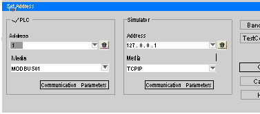
On the PC, click the Control Expert PLC\Set Address tab to bring up the Set Address menu.
 |
|
4
|
Select MODBUS01 in the PLC Media field.
|
|
5
|
Enter the Modbus address in the PLC Address field (the default address is 1).
Note: You can also use the keypad on the 140 CPU 651 50 module to enter or change the Modbus address.
|
|
6
|
Click OK.
|
|
7
|
Proceed to Downloading and Running the Configuration Program (below).
|
|
Step
|
Action
|
|---|---|
|
1
|
On the PC, select PLC \Connect on the Control Expert screen.
|
|
2
|
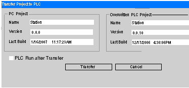
Click the PLC\Transfer Project to PLC tab to bring up the Transfer Project to PLC dialog box.
 |
|
3
|
Click the Transfer button to download the program to the PLC.
|
|
4
|
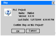
When the confirm screen appears, click OK.
 |
|
5
|
Click Run on the Control Expert upper toolbar to start the program.
|