The safety function is autonomous in relation to PLC operation.
It does not follow the PLC operating modes.
It is able to shut off power even when the PLC is off, in Stop mode or if the CPU is missing. It is not a safety PLC.
The only exchange between the CPU and the module is diagnostic information transferred from the module to the CPU.
The PLC is constantly informed of the status of the safety system via input data.
NOTE: The PLC has no control over any output.
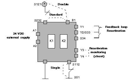
The product diagram is shown below:
The 24 Vdc supply is cabled between terminals A1 and A2. It must be protected by an external fuse.
Using SS ESD and PS single/double contacts
The way in which the B1 terminal is wired makes it possible to choose the type of single or double SS ESD:
-
If B1 is linked to S121, the module is wired with double contacts between terminals S121 and S232 for the positive pole, and between terminals S01and S112 for the negative pole.
-
If B1 is linked to S232, the module is wired with single contacts between terminals S121 and S232 for the positive pole, and with a global shunt between terminals S01and S112 for the negative pole.
Using SS ESD and PS contacts
Pressing one of the emergency stop buttons or a cut in external supply leads directly to the opening of the K1 and K2 safety output circuits,
After unlocking the SS ESD or closing the PS of the input sequence, a pulse to the activation input (terminals S33-S34) will allow the closing of safety output contacts (terminals 13-14 and 23-24).
The safety system is reactivated when the feedback loop between terminals Y1 and Y2 is closed AND when there is a reactivation request (S24) between terminals S33 and S34.
Terminals Y3/Y4 allow one to choose whether or not this reactivation is to be monitored:
-
When Y3/Y4 is open, the outputs are activated (recommended) when the PB is pressed then released (falling edge on S34)
-
When Y3/Y4 is closed, the outputs are immediately activated when the PB is pressed
A shunt on both Y3-Y4 and S33-S34 allows the outputs to be activated automatically as soon as the two input channels are closed. A de-synchronization time of 400 ms is allowed.
The TSX PAY 262 module features two outputs wired between terminals 13-14 and 23-24; these two outputs can be supplied independently.
The relays (with guided contacts) or switches connected upstream from the outputs must be inserted in the feedback loop between terminals Y1 and Y2. The device may only be switched on if those relays with safety-related functions which received a stop order have been deactivated. The feedback loop must be closed before any new start-up.
An additional external condition, managed by the API, may be inserted into the feedback loop to inhibit any reactivation in the event of a safety system fault being detected.
