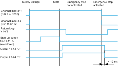
This section provides the functional diagrams for the emergency stop functions and the protective cover with automatic start-up.
The following diagram shows the functional diagram for the emergency stop function:
Depending on the wiring of Y3-Y4, reactivation is carried out on edge or on state.
A single open SS ESD contact opens the safety outputs.
Both channels must be open to allow reactivation to take place: this constitutes self-checking of inputs.
Reactivation is only possible if the Y1-Y2 loop is closed: this self-checks the outputs.
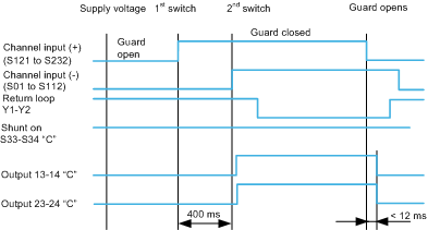
Protective cover function with automatic start-up
The following diagram shows the functional diagram for the protective cover function with automatic start-up:
The use of the two distinct PSs (switch 1 and 2) requires the mechanical elements to respect a time delay of less than 400 ms upon closure of the 2 switches.
The manufacturer's characteristics guarantee inhibition of the command if the time is greater than 1 s. In this configuration, the automatic reactivation is selected.