|
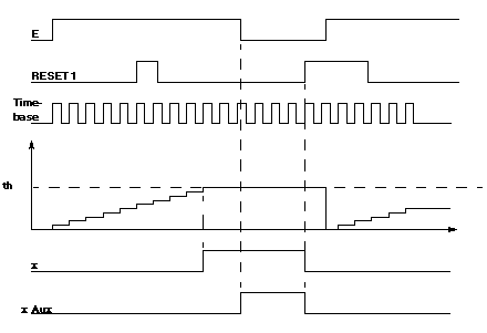
Reflex function block: 1 threshold intervalometer
|
|
|
(Original Document)
|
|
Name
|
Meaning
|
|---|---|
|
E
|
Intervalometer initialization input.
|
|
RESET 1
|
Outputs x and x Aux are set to 0.
|
|
ti
|
Time-base (0.1ms to 6.5535 s).
|
|
x
|
Intervalometer's physical output.
|
|
x Aux
|
Block's internal auxiliary output.
|
|
Illustration
 |
|
|
Phase
|
Description
|
|---|---|
|
1
|
On the rising edge of input E :
|
|
2
|
Counter increases at the rate of time-base ti.
|
|
3
|
When threshold th is reached, output x changes to 1.
|
|
4
|
On the falling edge of input E with output x at 1, output x Aux changes to 1.
|
