|
Reflex function block: Single electronic CAM
|
|
|
(Original Document)
|
|
Name
|
Meaning
|
|---|---|
|
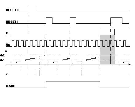
E
|
Enable input.
|
|
Up
|
Counting input.
Note: the maximum performance of the counter is 2 Khz (with the Up input directly controlled by the physical input (without filtering)).
|
|
RESET 0
|
Output x forced to 0.
|
|
RESET 1
|
Counter initialization input.
Note: If the counter is not reset to 0, when it reaches the maximum value (65536 points), it will change to 0,1,2 etc. Therefore it is advisable to inhibit counting (E=0) by using the x Aux output in series with output E.
|
|
x
|
Cam's physical output.
|
|
x Aux
|
Block's internal auxiliary output.
|
|
Illustration
 |
|
|
Phase
|
Description
|
|---|---|
|
1
|
On the rising edge of input RESET 1:
On the high status of input RESET 0:
|
|
2
|
On the rising edge of input Up, the counter is increased.
|
|
3
|
When threshold th1 is reached, output x changes to 1.
|
|
4
|
When threshold th2 is reached, outputs x and x Aux change to 0.
|
