|
Reflex Function Block: 2 Threshold Counter
|
|
|
(Original Document)
|
|
Name
|
Meaning
|
|---|---|
|
E
|
Enable input.
|
|
Up
|
Counter input.
Note: Maximum performance of the counter is 500 Hz with a 50% duty cycle (with the Up input directly controlled by the physical input (without filtering)).
|
|
RESET
|
Counter initialization input.
A Reset is required to acknowledge a change in the value of the threshold to be reached.
|
|
Sel
|
Selection of the counting threshold:
Note: The maximum value of a threshold corresponds to the maximum number of pulses (65536 pulses).
|
|
x
|
Counter physical output.
|
|
x Aux
|
Block internal auxiliary output.
|
|
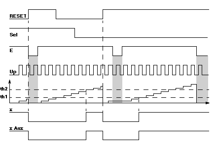
Illustration
 |
|
|
Phase
|
Description
|
|---|---|
|
1
|
On the rising edge of the RESET input:
|
|
2
|
On the rising edge of the Up input, the counter is incremented (value not accessible).
|
|
3
|
When the selected threshold is reached, the x and x Aux inputs switch to 1.
|
