At a Glance
There are two versions, available in two types of 40-pin terminal blocks:
| Standard version |
|
| Hardened version |
|
The hardened version of the terminal blocks are only dedicated to the hardened version of the modules.
| WARNING | |
|---|---|
There are also preassembled cordsets with a BMX FTB 4020 terminal block at one end and flying leads at the other. The cordsets are available under reference BMX FTW ••5.
Cable Ends and Contacts
The 40-pin terminal blocks are designed for only one wire or one cable end.
Each terminal block can accommodate:
Bare wires:
Solid conductor
Stranded cable
Wires with ferrule (DZ5CE••••/DZ5CA•••• single type cable ends):

Jumper bar
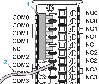
To facilitate the wiring, a 20-pin jumper bar with plastic handle is provided with 40-pin caged screw terminal block BMX FTB 4000:

The following graphic shows an example of using the jumper bar for non-isolated wiring channel 0-2 with on a BMX DRC 0805 module:

1 Jumper bar
2 to common
| CAUTION | |
|---|---|
Description of the 40-pin Terminal Blocks
The following table describes the type of wires that fit each terminal block and the associated gauge range, wiring constraints, and tightening torque:
Caged Terminal Blocks BMX FTB 4000 |
Spring Terminal Blocks BMX FTB 4020 |
|
|---|---|---|
Illustration |
 |
 |
1 solid conductor
|
|
|
1 stranded cable
|
|
|
1 stranded cable with ferrule
|
|
|
Minimum individual wire size in stranded cables when a ferrule is not used
|
|
|
Wiring constraints |
Caged terminal blocks have slots that accept:
Caged terminal blocks have captive screws. On the supplied blocks, these screws are not tightened. |
The wires are connected by pressing the button located next to each pin. To press the button, use a flat-tipped screwdriver with a maximum diameter of 3 mm. |
Screw tightening torque |
0.4 N•m (0.30 lbf-ft) |
Not applicable |
Connection of 40-pin Terminal Blocks
| DANGER | |
|---|---|
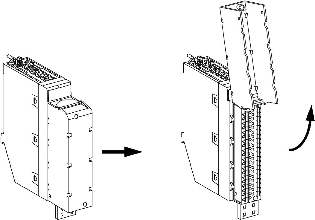
The following diagram shows the method for opening the terminal block cover so that it can be wired.

The connection cable is installed and held in place by cable clamps positioned below the terminal block.
Labeling the Terminal Blocks
The labels for the terminal blocks are supplied with the module. They are to be inserted in the terminal block cover by the customer.
Each label has two sides:
One side that is visible from the outside when the cover is closed. This side features the commercial product references, an abbreviated description of the module, as well as a blank section for customer labeling.
One side that is visible from the inside when the cover is open. This side shows the terminal block connection diagram.


