Introduction
40-pin connector modules are connected to sensors, pre-actuators, or terminals using a cable designed to enable trouble-free direct wire to wire transition of the module’s inputs/outputs.
| DANGER | |
|---|---|
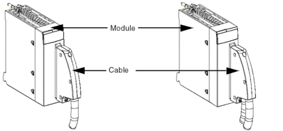
The following diagram shows the connection of the cable to the module.
| WARNING | |
|---|---|
BMX FCW ••• Connection Cables
They are made up of:
- at one end, a compound-filled 40-pin connector from which extend 1 or 2 cable sheaths, each containing 20 wires with a cross-sectional area of 0.34 mm2 (AWG 22)
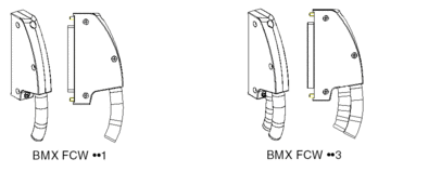
at the other end, free wire ends color coded
The cables with 1 cable sheath containing 20 wires designed to connect the 40-pin connectors to the sensors or pre-actuators come in 3 different lengths:
3 meters: BMX FCW 301
5 meters: BMX FCW 501
10 meters: BMX FCW 1001
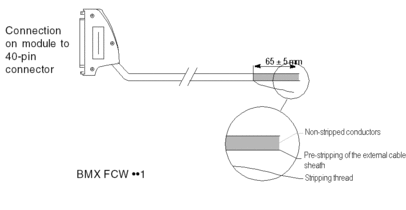
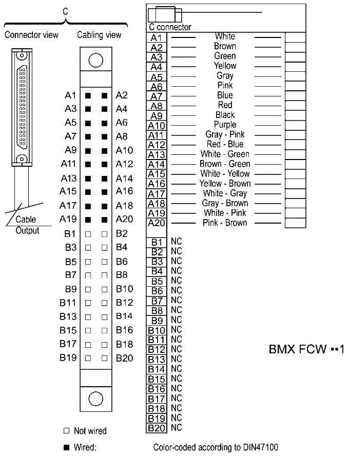
The figure below shows the BMX FCW ••1 cables.
The cables with 2 cable sheaths containing 20 wires designed to connect the 40-pin connectors to the sensors or pre-actuators come in 3 different lengths:
3 meters: BMX FCW 303
5 meters: BMX FCW 503
10 meters: BMX FCW 1003
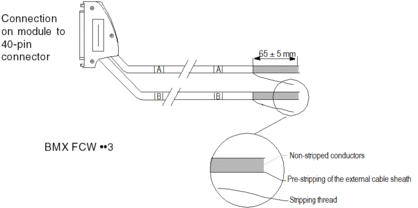
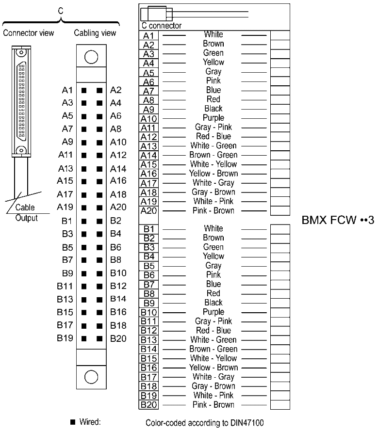
The figure below shows the BMX FCW ••3 cables.
| WARNING | |
|---|---|
Connection of BMX FCW ••• Cables
The diagram below shows the connection of BMX FCW ••1 cables:
The diagram below shows the connection of BMX FCW ••3 cables:
BMX FCW ••• Cables Characteristics
This table presents the general characteristics:
Characteristics |
Values |
|
|---|---|---|
Cable |
Sheath material |
PVC |
LSZH status |
No |
|
Conductor description |
Number of conductors |
|
Gauge |
0.34 mm2 (22 AWG) |
|
Material |
Tinned copper |
|
Environmental |
Operating temperature |
-25...70 °C (-13....158 °F) |
Applicable standards |
DIN47100 |
|


