At a Glance
Discrete inputs/outputs feature protective measures which ensure a high resistance to industrial environmental conditions. Nevertheless, the rules described below must be followed.
External Power Supplies for Sensors and Pre-Actuators
Use quick-blow fuses to protect external sensor and pre-actuator power supplies associated with discrete input/output modules against short-circuits and overloads.
For 40-pin connector discrete input/output modules, link the sensor/pre-actuator power supply to each connector, except in the event where the corresponding channels are not in use and are not assigned to any task.
| DANGER | |
|---|---|
Inputs
Recommendations for use concerning the inputs of discrete modules are as follows:
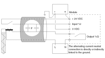
for 24 VDC inputs and line coupling with an alternating current network:
WARNING This case (excessive coupling) is illustrated in the following circuit diagram.
When the input contact is open, the alternating currents may induce a current in the input which might cause it to be set to 1.
For a 240 VAC/50 Hz line coupling, do not exceed the line capacitance values given in the summary table at the end of this section. For a coupling with a different voltage, use the following formula:

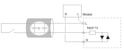
for 24 to 240 VAC inputs and line coupling:
When the line that controls the input is open, the current passes according to the coupling capacitance of the cable (see circuit diagram below).
Do not exceed the line capacitance values given in the summary table below.
The following summary table shows the acceptable line capacitance values.
Module |
Maximum coupling capacitance |
|
|---|---|---|
24 to 125 VDC inputs |
||
BMX DDI 1602 BMX DDI 1603 BMX DDI 1604T BMX DDM 16022 BMX DDM 16025 |
45 nF (1) |
|
BMX DDI 3202 K BMX DDI 6402 K BMX DDM 3202 K |
25 nF (1) |
|
24 to 140 VAC inputs |
||
BMX DAI 0805 BMX DAI 1615 |
50 nF |
|
BMX DAI 1602 |
50 nF |
|
BMX DAI 1603 |
60 nF |
|
BMX DAI 0814 BMX DAI 1614 BMX DAI 1604 |
70 nF |
|
(1) max. admissible coupling capacitance with a 240 VAC / 50 Hz linemax. admissible coupling capacitance with a 240 VAC / 50 Hz line |
||
Example: A standard cable of 1 m in length has a coupling capacity that falls within 100 and 150 pF.
Outputs
For the outputs of discrete I/O modules, follow the recommendations described here.
| WARNING | |
|---|---|
Cable Routing
| WARNING | |
|---|---|
Precautions for use to be taken concerning the wiring system are as follows:
in order to reduce the number of alternating couplings, separate the power circuit cables (power supplies, power switches, etc.) from input cables (sensors) and output cables (pre-actuators) both inside and outside the equipment
outside the equipment, place the cables leading to inputs/outputs in covers that make them easily distinguishable from those containing wires relaying high energy levels. Place them in separate metal cableways which are grounded. Route these various cables at least 100 mm (4 in.) apart


