All connections or disconnections on the TELEFAST must be made when SWITCHED OFF (encoders, link to counting module, links between TELEFAST bases).
Connecting TELEFAST 0 to TELEFAST counting and chaining module
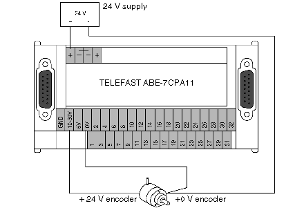
The TSX CCP S15 (2.5m), TSX CCP S15100 (1m) and TSX CCP S15050 (0.5m) cables are offered for connecting TELEFASTS amongst themselves or for connecting TELEFAST 0 to the TSX CTY 2C module. The user can however carry out longer links by using the wiring kit, reference no. TSX CAP S15••, and by respecting the following setpoint when the encoders have a 5 V supply : if the link between the counting module and the TELEFAST 0 does not exceed 100m, use gauge 28 wires (0.008mm2). If it is > 100m, use wires with at least gauge 22 (0.34mm2). However, to limit the drop in voltage at 0 V (due to the encoder supply current), we recommend that you wire the 0 V according to the following diagram.
Wiring diagram:
Cable length between counting module and TELEFAST
The total length of the link between the counting module and the TELEFAST (sum of the lengths between the counting channel and the first TELEFAST and the different TELEFAST between one another) must not exceed 200m, in the knowledge that the maximum cable length between 2 TELEFAST is 50m.
If the total distance between the first and the last TELEFAST exceeds 20m, the line on the right connector of the last TELEFAST must be adapted by inserting an end-of-line stopper (220 Ω resistance between pins 1 and 2 of the connector).
The following table shows the serial transmission clock frequencies, according to the total length of the link:
|
Cable lengths
|
Frequency of the serial transmission clock
|
|
< 10m
|
1 MHz
|
|
< 20m
|
750 kHz
|
|
< 50m
|
500 kHz
|
|
< 100m
|
375 kHz
|
|
< 150m
|
200 kHz (default)
|
|
< 200m
|
150 kHz
|
Protecting the encoder supply
The voltage used by the encoder(s) connected to TELEFAST determine whether this supply should be 10…30 VDC or 5 VDC. If the supply is 10…30 VDC, the protective fuse is built-in to the TELEFAST (fast-blow 1A fuse). However, if the TELEFAST has a supply of 5 VDC, the user must provide in series with the +supply terminal a fast-blow fuse, which is adapted to TELEFAST consumption and to the encoders connected.
Monitoring the encoder supply voltage
This function is only valid if a single encoder is connected to the TELEFAST. If the encoder supply voltage decreases by more than 15%, the default EPSR is sent back to the module.
If the encoder does not have an encoder supply feedback, you must wire:
-
the TELEFAST +EPSR terminal to the + of the encoder supply,
-
the TELEFAST -EPSR terminal to the - of the encoder supply.
Wiring the encoder outputs
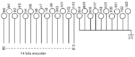
If the encoder outputs have positive logic and there are less than 24 of them, the following rules must be adhered to:
-
wire the encoder outputs to the TELEFAST inputs, working up from the least to the most significant,
-
wire the unused TELEFAST inputs to the 0 V terminal.
Illustration:
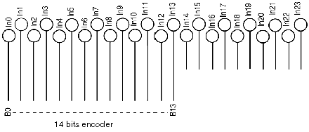
If the encoder outputs have negative logic, and there are less than 24 of them, the following rules must be adhered to:
-
wire the encoder outputs to the TELEFAST inputs, working from the up from the least to the most significant,
-
do not wire the unused TELEFAST inputs (leave loose).
Illustration:


