|
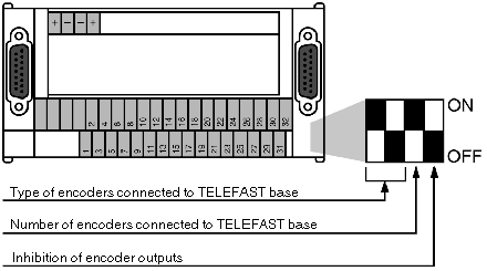
Configuration of the TELEFAST base
|
|
|
(Original Document)
|

|
Illustration
|
Description
|
|---|---|
 |
The encoder outputs are at high impedance with a 3ST0 or 3ST1 command active at 0.
|
 |
The encoder outputs are at high impedance with a 3ST0 or 3ST1 command active at 1.
|
|
Illustration
|
Description
|
|---|---|
 |
An encoder is connected to the base.
|
 |
Two encoders are connected to the base.
|
|
Hardware configuration (number of encoders per TELEFAST)
|
TELEFAST micro-switch
|
Address
|
Action
|
||
|
0
|
1
|
AD0
|
AD1
|
||
|
2 encoders on TELEFAST 0 and
1 encoder on TELEFAST 1
|
ON
|
ON
|
0
0
1
1
|
0
1
0
1
|
Reading the TELEFAST 0 encoder 0
Reading the TELEFAST 0 encoder 1
Reading the TELEFAST 1 encoder
Reading the TELEFAST 1 encoder
|
|
1 encoder on TELEFAST 0 and
2 encoders on TELEFAST 1
|
ON
|
ON
|
0
0
1
1
|
0
1
0
1
|
Reading the TELEFAST 0 encoder
Reading the TELEFAST 0 encoder
Reading the TELEFAST 1 encoder 0
Reading the TELEFAST 1 encoder 1
|
|
Hardware configuration (number of encoders per TELEFAST)
|
TELEFAST micro-switch
|
Address
|
Action
|
|||
|
0
|
1
|
2
|
||||
|
1 encoder on TELEFAST 0
1 encoder on TELEFAST 1
and
1 encoder on TELEFAST 2
|
ON
|
OFF
|
OFF
|
0
0
1
1
|
0
1
0
1
|
Reading the TELEFAST 0 encoder
Reading the TELEFAST 0 encoder
Reading the TELEFAST 1 encoder
Reading the TELEFAST 2 encoder
|
|
1 encoder on TELEFAST 0
1 encoder on TELEFAST 1
and
1 encoder on TELEFAST 2
|
OFF
|
ON
|
OFF
|
0
0
1
1
|
0
1
0
1
|
Reading the TELEFAST 0 encoder
Reading the TELEFAST 1 encoder
Reading the TELEFAST 1 encoder
Reading the TELEFAST 2 encoder
|
|
1 encoder on TELEFAST 0
1 encoder on TELEFAST 1
and
1 encoder on TELEFAST 2
|
OFF
|
OFF
|
ON
|
0
0
1
1
|
0
1
0
1
|
Reading the TELEFAST 0 encoder
Reading the TELEFAST 1 encoder
Reading the TELEFAST 2 encoder
Reading the TELEFAST 2 encoder
|
|
Encoders with positive logic outputs, Totem pole outputs, TTL outputs and NPN open collector outputs coded in Gray
|
Max.length
encoder/
TELEFAST
|
Max. frequency for changing least significant bit
|
|---|---|---|
 |
50 m
|
75 kHz
|
|
Encoders with negative logic outputs, Totem pole outputs, TTL outputs and NPN open collector outputs coded in Gray
|
Max.length
encoder/
TELEFAST
|
Max. frequency for changing least significant bit
|
|---|---|---|
 |
50 m
|
75 kHz
|
 |
100 m
|
40 kHz
|
 |
200 m
|
5 kHz
|
|
Encoders with positive or negative logic outputs,
NPN open collector, binary coded
|
Max. length
encoder/
TELEFAST
|
Max. frequency
for changing least significant bit
|
|---|---|---|
 |
10 m
|
40 kHz
|
 |
30 m
|
20 kHz
|
 |
50 m
|
5 kHz
|