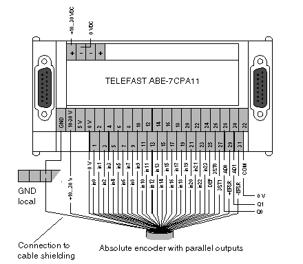
|
|
(Original Document)
|

|
Signals
|
Meaning
|
Terminal No.
|
|---|---|---|
|
GND
|
ground connection of the encoder(s)
|
|
|
+10…30 V
|
+ supply terminal of the encoder(s)
|
|
|
0 V
|
- supply terminal of the encoder(s)
|
|
|
in0 to in23
|
outputs of the encoder(s)
|
1...24
|
|
ERR
|
error output of the encoder(s)
|
25
|
|
3OT0
|
command to inhibit the 0 encoder outputs (for multiplexing)
|
26
|
|
3OT1
|
command to inhibit the 1 encoder outputs (for multiplexing)
|
27
|
|
AD0, AD1
|
encoder multiplexing command
|
28,30
|
|
COM
|
shared AD0 and AD1 signals
|
32
|
|
+ EPSR
|
encoder supply return input + (connector at 10…V if no monitoring)
|
29
|
|
- EPSR
|
encoder supply return input + (connector at 0 V without monitoring)
|
31
|