|
Physical Description
|
|
|
(Original Document)
|

|
No.
|
Description
|
|---|---|
|
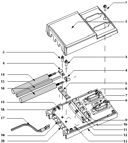
1
|
Cover screws
|
|
2
|
Device cover
|
|
3
|
Screws fixing restart ground clamps
|
|
4
|
Restart ground clamps
|
|
5
|
Metallic part providing the ground link between the 2 cables
|
|
6
|
SUB D 15 pin female (JM) connector able to receive:
|
|
7
|
1 micro-switch allowing configuration in 2-or 4-wire operation
|
|
8
|
SUB D 15 pin female (JS) connector able to receive:
|
|
9
|
4 micro-switches allowing polarization mode to be configured
|
|
10
|
Terminal to connect green/yellow ground wire
|
|
11
|
Connection terminals for the main connection cables providing bus continuity
|
|
12
|
Device connection base
|
|
13
|
Screw holes (4 diameter) to fix the device to a board or panel (60mm apart)
|
|
14
|
Main 2 or 3 pair cable providing bus continuity (max. 10 diameter), for connection to JA
|
|
15
|
5VDC power supply cable (for external polarization if required) for connection to JC
|
|
16
|
Main 2 or 3 pair cable providing bus continuity (max. 10 diameter), for connection to JB
|
|
17
|
Green/yellow device grounding cable
|
|
18
|
Main cable with corresponding ground format connected to local ground via a surge suppressor
|
|
19
|
Power supply cable and green/yellow ground wire
|
|
20
|
Main cable with corresponding ground format connected to local ground
|