|
About the TSX IBX 100 Module
|
|
|
(Original Document)
|


|
Number
|
Type of element
|
Function
|
|---|---|---|
|
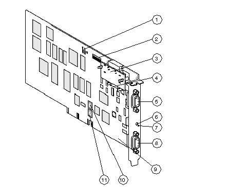
1
|
Signaling block
|
It is composed of 7 indicator lights for viewing the state of the module and for carrying out a diagnostic.
|
|
2
|
Micro-switches
|
Rack addresses and module positions can be coded using these switches.
|
|
3
|
Line terminator A/ of X Bus
|
Adapts the X Bus line impedance.
|
|
4
|
Connector
|
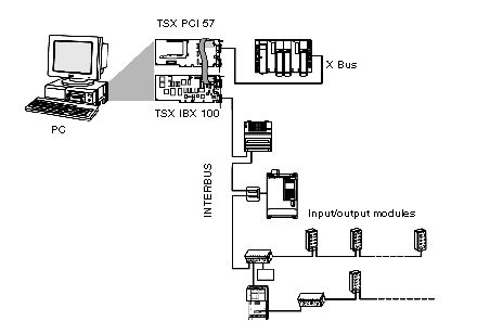
Used to link X Bus to the PCX PCI 57 processor.
|
|
5
|
9-pin female RS 232 Sub-D connector
|
Used to connect a PC equipped with CMD Tool software.
|
|
6
|
RESET pencil-point button
|
Initiates a warm restart of the module when it is activated.
|
|
7
|
ERR LED
|
-
|
|
8
|
9 pin female RS 485 Sub-D connector
|
Used to connect the INTERBUS field bus.
This connector acts as the arrival and departure point on an interstation bus (ring topology).
|
|
9
|
16 bit ISA connector
|
Used to connect the PC host, enabling the use of the CMD Tool software (if installed on the terminal).
|
|
10
|
Pivotable IRQ micro-switches
|
Used to select the IRQ switch, used by the internal RS 232 port on the ISA bus.
|
|
11
|
Pivotable address micro-switches
|
Used to code the input/output addresses on the internal RS 232 port.
|