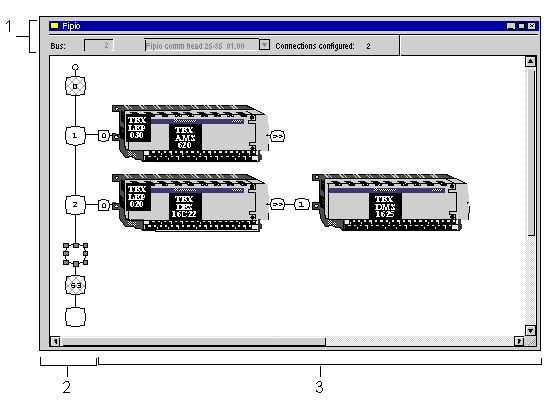
Fipio Bus Configuration Screen
(Original Document)
At a Glance
This screen is used to declare devices which are connected to the bus.
Illustration
The Fipio communication screen looks like this:
Elements and Functions
This table describes the different areas that make up the configuration screen:
Number
Element
Function
1
Bus
Bus number.
Connections configured
Indicates the number of connection points configured (0 and 63 are not counted).
2
Logical address area
This area consists of:
  • slot 0 (manager),
  • the addresses of each device,
  • free addresses between 0 and 63 and over 63,
  • address 63 is reserved for the programming terminal.
3
Module area
This area contains the devices (base and extension modules, and the communicator if necessary) which are connected to the bus.
Gray squares on the bus indicates the two reserved addresses:
Available connection points are indicated by a white square with rounded edges.