|
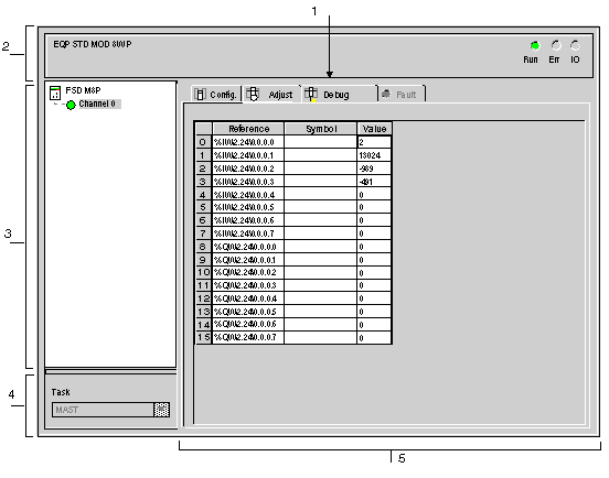
Debug Screen for a Standard Profile
|
|


|
(Original Document)
|
|
Debug Screen for a Standard Profile
|
|
|
(Original Document)
|
|
Number
|
Element
|
Function
|
|---|---|---|
|
1
|
Tabs
|
The tab in the foreground indicates the mode in progress (Debug in this example). Each mode can be selected using the respective tab. The available modes are:
|
|
2
|
Module area
|
Gives a reminder of the device’s shortened name.
In the same area there are 3 LEDs which indicate the module’s operating mode:
|
|
3
|
Channel area
|
Is used:
|
|
4
|
General parameters area
|
This area is used to display the type of task (MAST or FAST) in which the channel implicit exchange objects are exchanged.
|
|
5
|
Parameters in progress area
|
In cases where for the standard profile the input bits, the %IW input words or the %QW output words exist, this area displays them.
A Reference, a Symbol and a Value are associated to each word.
For each value the contextual menu can be used to select the display base for the value of the selected word.
Three types are available:
For FRD ••• standard profile, the Error column provides direct access to the diagnostics for each channel when these are faulty (indicated by the indicator lamp built into the diagnostics access button, which turns red).
|
