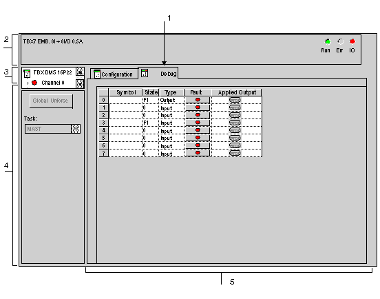
Debug Screen for a Device on the Fipio Bus
(Original Document)
At a Glance
In debug mode the following functions can be accessed by opening the application screen of a device:
Illustration
The figure below represents a debug screen.
Description
The following table shows the different elements of the debug screen and their functions.
Number
Element
Function
1
Tabs
The tab in the foreground indicates the mode in progress (Debug in this example). Each mode can be selected using the respective tab.
  • Debug which can be accessed only in online mode,
  • Calibration which can be accessed only in online mode,
  • Configuration,
  • Adjust.
2
Module area
Specifies the abbreviated heading of the module.
In the same area there are 3 LEDs which indicate the module’s operating mode:
  • RUN indicates the operating status of the module,
  • ERR indicates an internal fault in the module,
  • I/O indicates a fault from outside the module or an application fault.
3
Channel area
Is used:
  • By clicking on the reference number, to display the tabs:
    • Description which gives the characteristics of the device.
    • I/O Objects which is used to presymbolize the input/output objects.
    • Fault which shows the device faults (in online mode).
  • To select the required channel or channel group; to the left of the symbol there is a copy of theCHx channel LED.
4
General parameters area
Provides a reminder of the channel settings (Task type) and gives access to various functions (Global Unforce, etc.).
5
Parameters in progress area
This area displays the state of the inputs and outputs, and the different parameters in progress.
Specific Parameters
Refer to the documentation of each device for information on the general, configuration, adjustment and debugging parameters available.
For input/output modules, the specific parameters area shows the value and state of each of the module channels and gives access to the channel commands.