|
|
Original instructions
|
|
Step
|
Action
|
|---|---|
|
1
|
Open your application using the TSX ETY 4103 module in Control Expert.
|
|
2
|
In the Project Browser, locate the Communication → Networks directory.
|
|
3
|
Click the Ethernet module (TSX ETY 4103 in our example) to open the configuration screen.
|
|
4
|
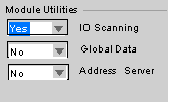
In Module Utilities, select Yes in the I/O Scanning menu.
 |
|
5
|
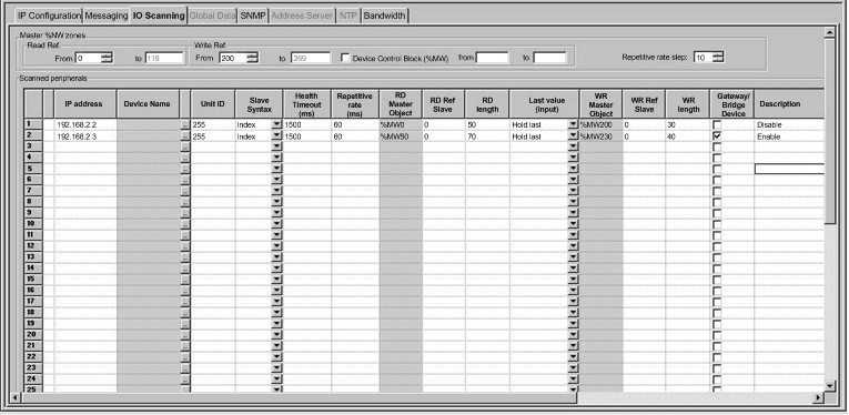
Click the I/O Scanning tab to display the I/O scanning configuration screen.
 |
|
6
|
Enter the parameter settings under each of the column headings for one line of the I/O Scanner Configuration. Refer to the following I/O Scanning Parameters topic to see the settings used for this example.
|
|
7
|
Click the validate check box in the upper tool bar to confirm the I/O scanning parameter settings.
 |
|
Parameter
|
Field
|
Description
|
|---|---|---|
|
Read Ref.
|
From and to check boxes
|
The values in these boxes define the range of destination address values in the CPU for the data read from each device. The addresses you enter here are displayed in the RD Master Object column of the dialog. In the example above, the Read Ref. values range from 0 to 599; notice that these values are displayed as %MW0, %MW599, etc. in the Master Object column.
|
|
Write Ref.
|
From and to check boxes
|
The values in these boxes define the range of source address values in the CPU. The address you enter here is displayed in the WR Master Object column. In the example above, values starting at %MW2000 are shown in the WR Master Object column.
|
|
Device Control Block
|
check box
|
If this check box is selected, the device control block is enabled and the master can send requests to a slave. If the check box is not selected, the device control block functionality is disabled and all I/O scanner table entries are active at all times.
|
|
From and to check boxes
|
If a Device Control Block bit is disabled, the I/O scanner closes the connection and sets the health bit to an unhealthy state (bit value = 1).
|
|
|
Repetitive Rate Step
|
data box
|
The Repetitive Rate Step is set in multiples of 5 ms (the minimum) through 200 ms (the maximum).
The Repetitive Rate column is where you enter a rate of time for how often you want the I/O scanner to send a query to the device after the rate has timed out.
NOTE: The Repetitive Rate of the I/O scanner table is a multiple of the rate displayed in the Repetitive Rate Step. The real repetitive rate being executed by the I/O scanner service is shown in the Repetitive Rate column. NOTE: An entry in the Repetitive Rate column is rounded up to the next multiple that was entered in the Repetitive Rate Step box if the entry is not a multiple of the Repetitive Rate Step.
For example, if the entry in the Repetitive Rate Step is 5 and you enter a 7 in the Repetitive Rate column, the 7 is rounded up to 10; if you change the Repetitive Rate Step to 6 and enter a 7 in the Repetitive Rate column, the 7 is rounded up to 12. |
|
Parameter
|
Description
|
Example
|
|---|---|---|
|
Entry #
|
This is the first column; it has no name.
Valid range: 1 ... 128
Each entry represents an I/O Scanning exchange on the network.
|
|
|
IP address
|
This is the IP address of the scanned Ethernet slave device.
|
192.168.1.100
|
|
Device Name
|
To configure a device (Advantys island or DTM), click the ... button to open the Property box to start the device configuration software.
For an introduction to this procedure for Advantys, go here.
For an introduction to this procedure for DTMs, go to FDT Container.
NOTE: While the Property box is open, I/O scanning cannot be edited. |
MySTB1 or Master_PRM_DTM_10
|
|
Unit ID
|
This field associates the slave address of the device connected to an Ethernet/Modbus gateway with the IP address of that gateway:
When using a bridge, enter the bridge index (1 to 255) in this field.
|
255
|
|
Slave Syntax
|
Use this drop-down menu to pick the way RD Ref Slave and WR Ref Slave values are displayed. The 4 choices are (with an example):
|
Index (default value)
|
|
Health Timeout (ms)
|
This field sets the maximum interval between the responses from a remote device. After this time period expires, the received data is invalid. The Health Timeout must be longer than the Repetitive Rate time (ms). For a Premium ETY Ethernet module, it must be longer than the CPU scan time.
For the Health Timeout:
|
1500 ms
|
|
Repetitive rate (ms)
|
The rate at which data is scanned, from 0...50000 in multiples of the Repetitive Rate Step:
|
60 ms
|
|
RD Master Object*
|
Destination address in the master PLC where, from each device, newly read information is stored
|
%mw10
|
|
RD Slave Ref.**
|
Source address index in the slave/remote device
|
The format of this value depends on the Slave Syntax:
|
|
RD length
|
Number of words to read
|
10
|
|
Last value (Input)
|
This field configures the behavior of inputs in the event of an access error in relation to the remote device (for example: inoperative network or device power supply, etc.):
|
Hold last
|
|
WR Master Object*
|
Source address of the master PLC whose data is being written into the slave/remote device.
Write operations are always performed at the word level.
|
%mw20
|
|
WR Slave Ref.**
|
The address of the first word written into the slave/remote device.
|
The format of this value depends on the Slave Syntax:
|
|
WR length
|
Number of words to be written
|
10
|
|
Gateway/Bridge Device
|
To allow slower TCP/IP network devices (i.e., gateways and bridges) to be compatible with the I/O Scanner:
|
|
|
Description
|
Additional information
|
|
|
*Master refers to the client PLC that makes the request.
**Slave refers to the server from which data is read or to which data is written.
|
||