Slave Diagnostics
(Original Document)
At a Glance
Slave diagnostics are only performed at the device level.
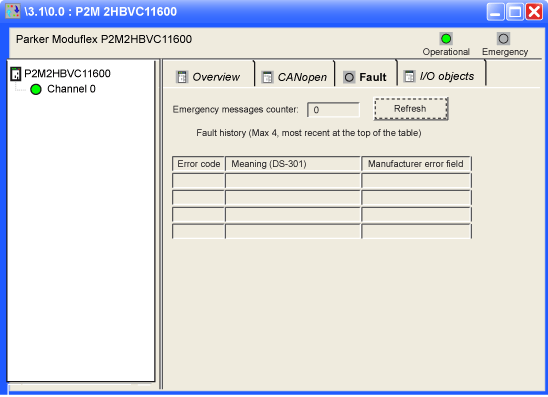
The slave diagnostic screen displays:
Illustration
The figure below shows a slave diagnostic screen:
Elements and Functions
The table below describes the different areas which make up the master debug screen:
Read
Number
Channel
1
Tab
The tab in the foreground indicates the type of screen displayed. In this case, the diagnostic screen.
2
Module
This area is made up of the abbreviated heading of the module equipped with a CANopen port, as well as 2 LEDs indicating the status of the module.
3
Channel
This area allows you to select the communication channel to be debugged.
By clicking on the device, you display the tabs:
  • Overview: gives the characteristics of the device,
  • CANopen: allows read/write of SDO (online mode only),
  • Faults: allows you to see the last 4 emergency messages generated by the slave module (tab only accessible in online mode) (see manufacturer's documentation),
  • I/O Objects: allows pre-symbolizing of the input/output objects.
This area also has an LED indicating the channel status.
4
Display
This area is composed:
  • of detected error counters,
  • of the last 4 messages (the last received message is in the upper line).
NOTE: The error counter cannot be reset to 0.
NOTE: There is no polling on emergency messages. Messages are updated once after opening the screen only. The user can refresh them with the refresh button.
NOTE: The emergency messages counter is automatically refreshed. If some new messages appear, the back color of the refresh button becomes red to indicate that the user must refresh the list.