|
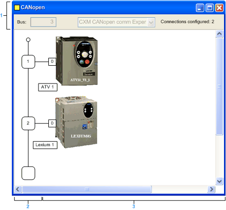
CANopen Bus Editor
|
|
|
(Original Document)
|

|
Number
|
Element
|
Function
|
|---|---|---|
|
1
|
Bus
|
Bus number.
|
|
Connections configured
|
Indicates the number of connection points configured.
|
|
|
2
|
Logical address area
|
This area includes the addresses of the devices connected to the bus.
|
|
3
|
Module area
|
This area includes the devices that are connected to the bus.
|