|
Advantys Software Configuration
|
|
|
(Original Document)
|
|
Step
|
Action
|
|---|---|
|
1
|
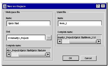
Open the Advantys software and create a new workspace (File → New workspace...) by indicating:
Result:
 the name of the project file will be Quick start.aiw and the file name of the Advantys STB will be Node_2.isl.
Note: All nodes for the same bus must be declared in the same project directory.
|
|
2
|
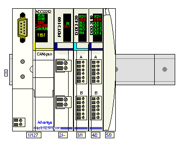
Configure Node_2 by dragging the modules from the hardware catalog located on the right side of the screen.
Result:
 Note: Be careful not to forget the STB XMP 1100 bus terminator.
|
|
3
|
Add a new island from the File menu, whose name will be Node_3.
|
|
4
|
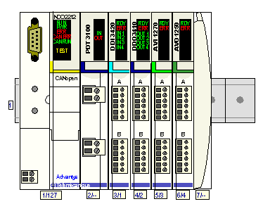
Repeat step 2 for Node_3.
Note: If you have forgotten the power supply, as well as the STB XMP 1100 terminator, you cannot display the configuration in online mode. You must then add them manually.
Result:
 |
|
5
|
Select Node_3 in the menu Island → I/O image preview to display the I/O image.
|
|
6
|
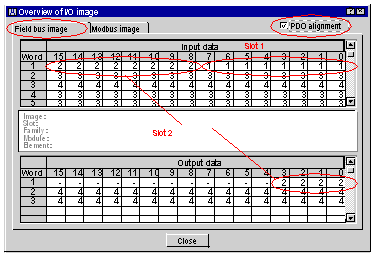
Click on the Field bus image tab and check the PDO alignment box to display the elements of node 3.
Result:
 Note: We see that node 3 has 3 output words and 5 input words. Inputs for slot 1 (DDI module) are located in the least significant byte of word 1. Module I/Os located at slot 2 (DDO module) are located in input word 1 (most significant) and its outputs in the output word 1, etc.
The general rules for mapping are explained in the remainder of this document.
|
|
7
|
Repeat step 6 for Node_2 in order to display the elements of node 2.
|
|
8
|
Select node 2 and create the EDS file by selecting the File → Export Node_2... option and naming it Node_2.
Note: In our example, the file will be saved in the following location: D:\Advantys_Projects\Quick Start\Node_2.eds.
|
|
9
|
Select node 3 and create the EDS file by selecting the File → Export Node_3... option and naming it Node_3.
Note: In our example, the file will be saved in the following location: D:\Advantys_Projects\Quick Start\Node_3.eds.
|
|
Input data
|
||||
|---|---|---|---|---|
|
Word
|
Bits 15 to 12
|
Bits 11 to 8
|
Bits 7 to 4
|
Bits 3 to 0
|
|
1
|
Status bits slot 2
|
Output echo bits slot 2
|
Status bits slot 1
|
Input bits slot 1
|
|
2
|
Status byte slot 3
|
Status byte slot 3
|
||
|
3
|
Status byte slot 4
|
Status byte slot 4
|
||
|
4
|
Analog inputs slot 3
|
|||
|
5
|
Analog inputs slot 4
|
|||
|
Output data
|
||||
|---|---|---|---|---|
|
Word
|
Bits 15 to 12
|
Bits 11 to 8
|
Bits 7 to 4
|
Bits 3 to 0
|
|
1
|
-
|
-
|
-
|
Output bits slot 2
|
|
2
|
Analog outputs slot 4
|
|||
|
3
|
Analog outputs slot 4
|
|||