|
Description
|
|
|
Original instructions
|
|
Operating mode
|
TR_S
|
START
|
|---|---|---|
|
Tracking
|
1
|
0 or 1
|
|
Autotuning
|
0
|
1
|

*Parameters of the autotuned controller (Para_PIDFF, Para_PI_B,etc.)

*Parameters of the autotuned controller (Para_PIDFF, Para_PI_B,etc.)
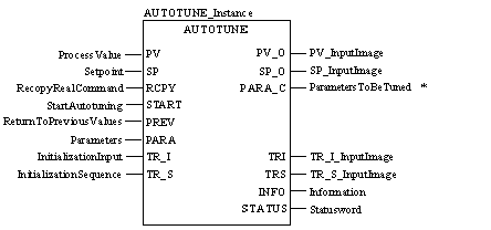
CAL AUTOTUNE_Instance (PV:=ProcessValue, SP:=Setpoint,
    RCPY:=RecopyRealCommand, START:=StartAutotuning,
    PREV:=ReturnToPreviousValues, PARA:=Parameters,
    TR_I:=InitializationInput, TR_S:=InitializationSequence,
    PV_O=>PV_InputImage, SP_O=>SP_InputImage,
    PARA_C=>ParametersToBeTuned, TRI=>TR_I_InputImage,
    TRS=>TR_S_InputImage, INFO=>Information,
    STATUS=>Statusword)
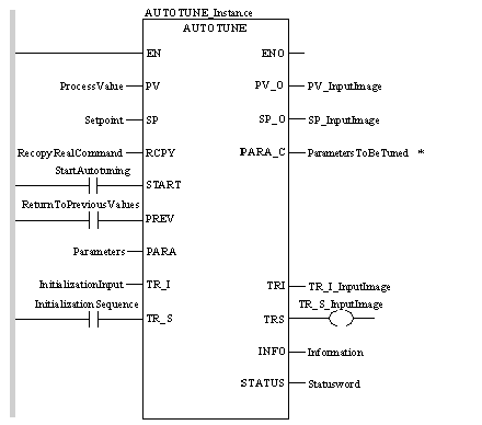
AUTOTUNE_Instance (PV:=ProcessValue, SP:=Setpoint,
    RCPY:=RecopyRealCommand, START:=StartAutotuning,
    PREV:=ReturnToPreviousValues, PARA:=Parameters,
    TR_I:=InitializationInput, TR_S:=InitializationSequence,
    PV_O=>PV_InputImage, SP_O=>SP_InputImage,
    PARA_C=>ParametersToBeTuned, TRI=>TR_I_InputImage,
    TRS=>TR_S_InputImage, INFO=>Information,
    STATUS=>Statusword) ;
|
Parameter
|
Data type
|
Meaning
|
|---|---|---|
|
PV
|
Process value
|
|
|
SP
|
REAL
|
Setpoint
|
|
RCPY
|
REAL
|
Copy of the actual manipulated variable
|
|
START
|
"0 → 1" : Starting the autotune
|
|
|
PREV
|
BOOL
|
Reverting to the previous controller settings
|
|
PARA
|
Parameter
|
|
|
TR_I
|
REAL
|
Start input
|
|
TR_S
|
BOOL
|
Start command
|
|
Parameter
|
Data type
|
Meaning
|
|---|---|---|
|
PV_O
|
REAL
|
Copy of the actual value PV
|
|
SP_O
|
REAL
|
Copy of the SP input
|
|
PARA_C
|
Parameters of the autotunable controller (Para_PIDFF or Para_PI_B)
|
Control parameters
|
|
TRI
|
REAL
|
Copy of the TR_I input
|
|
TRS
|
BOOL
|
Copy of the TR_S input
|
|
INFO
|
Information
|
|
|
STATUS
|
Status word
|
|
Element
|
Data type
|
Meaning
|
|---|---|---|
|
step_ampl
|
Value of the output actuating pulse (expressed in output scale values out_inf, out_sup)
|
|
|
tmax
|
Duration of the actuating pulse in automatic tuning
|
|
|
perf
|
REAL
|
Performance index between 0 and 1
|
|
plant_type
|
Reserved word
|
|
Element
|
Data type
|
Meaning
|
|---|---|---|
|
diag
|
Double word used for diagnosis
|
|
|
p1_prev
|
Previous value of parameter 1
|
|
|
p2_prev
|
REAL
|
Previous value of parameter 2
|
|
p3_prev
|
REAL
|
Previous value of parameter 3
|
|
p4_prev
|
REAL
|
Previous value of parameter 4
|
|
p5_prev
|
REAL
|
Previous value of parameter 5
|
|
p6_prev
|
REAL
|
Previous value of parameter 6
|
|
Base
|
Lower limit
|
Upper limit
|
|---|---|---|
|
Hexadecimal
|
16#0
|
16#FFFF
|
|
Octal
|
8#0
|
8#177777
|
|
Binary
|
2#0
|
2#1111111111111111
|
|
Data
|
Representation in one of the bases
|
|---|---|
|
0000000011010011
|
16#D3
|
|
1010101010101010
|
8#125252
|
|
0000000011010011
|
2#11010011
|
