|
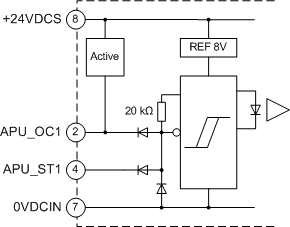
Sink Input Characteristics
|
|
|
Original instructions
|

 WARNING WARNING |
|
UNINTENDED EQUIPMENT OPERATION
Do not exceed any of the rated values in the characteristic table.
Failure to follow these instructions can result in death, serious injury, or equipment damage.
|
|
Characteristic
|
Value
|
|---|---|
|
Number of inputs per channel
|
One input per channel
0 V is common between the two channels
|
|
Type
|
Input is sink current to 0 V with two dedicated terminals:
|
|
Voltage limits
|
-0.5...+30 Vdc
|
|
Active state voltage
|
APU_OC or APU_ST less than 2 V
|
|
Passive state voltage
|
APU_OC or APU_ST greater than 2.5 V
|
|
Built in line polarization
|
APU_ST terminal provides a 20 kΩ pull up to 8 V
APU_OC terminal provides a 2 kΩ pull up resistor to 8 V then 10 kΩ up to 24 V
APU_OC terminal provides a dynamic 10 Ω pull up to 8 V on rising edge detection. 35 kHz signal can be detected up to 300 m for sensor to module without external pull-up adaptation.
|
|
Minimum pulse detected
|
1 μs
|
|
Maximum frequency
|
500 kHz
|