|
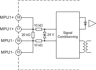
Differential Input Characteristics
|
|
|
Original instructions
|

 WARNING WARNING |
|
UNINTENDED EQUIPMENT OPERATION
Do not exceed any of the rated values in the characteristic table.
Failure to follow these instructions can result in death, serious injury, or equipment damage.
|
|
Characteristic
|
Value
|
|---|---|
|
Number of inputs per channel
|
One differential input per channel. Fully insulated cell.
|
|
Signal handling
|
Differential: Sinus or square wave
|
|
Built in input impedance
|
Resistive: 20 KΩ +/- 5% up to +/- 5 V
Resistive greater than 12 kΩ up to +/- 100 V
|
|
User input impedance
|
Two terminals for external resistor
|
|
Maximum input voltage from magnetic pickup (MPU) sensor
|
200 Vdc peak to peak simultaneously on both channels
|
|
Maximum input voltage from instrument potential transformer
|
150 Vac 50/60 Hz only for one channel
100 Vac 50/60 Hz simultaneous on both channels
|
|
Minimum input voltage(1) with sinus wave form (MPU sensor or PT)
|
Depending on parameter MPU input Mode configuration:
|
|
Minimum input voltage with square wave form (Encoder)
|
Depending on parameter MPU input Mode configuration:
|
|
Threshold (Immunity)
|
Depending on parameter MPU input Mode configuration:
|
|
Minimum pulse detected with MPU sensor
|
Time delay > 1.5 μs with U = +2.5 V
(Negative pulse is mandatory between pulses)
|
|
Maximum frequency
|
Square wave in Sensitive mode: 500 kHz
Square wave in Noisy mode: 250 kHz
Sinus wave in Sensitive mode: 250 kHz
Sinus wave in Noisy mode: 250 kHz
|
|
Minimum frequency with MPU sensor
|
Depending on parameter MPU input Mode configuration:
|
| (1) The pattern recognition system requires the input voltage to be greater than 4 V peak to peak in Noisy mode and 3 V peak to peak in Sensitive mode. (2) When the minimum input voltage and frequency levels are maintained, the threshold increases in line with the actual signal level. | |
 WARNING WARNING |
|
UNEXPECTED VALUES
Ensure that the minimum signal frequency levels are maintained.
Failure to follow these instructions can result in death, serious injury, or equipment damage.
|