|
Operating Modes
|
|
|
Original instructions
|

|
BMECXM State
|
Description
|
|---|---|
|
INITIALIZATION
|
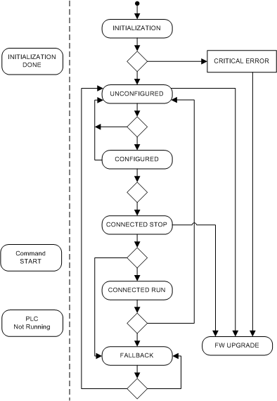
The module enters in this mode on power on or following up a reboot. The power on self-test (POST) is performed during this phase.
NOTE: When the power on self-test failed, the module switch to CRITICAL ERROR state. Refer to LEDs description to diagnose this state. |
|
UNCONFIGURED
|
The power on self-test is completed and the module proceed to:
|
|
CONFIGURED
|
The module has received its configuration file and is waiting for all expected EtherNet/IP connection with the PLC, as defined in the configuration file (.prm file).
After 5 s, if not all expected connections are opened, the BMECXM module restarts.
|
|
CONNECTED STOP
|
The boot slave procedure is started to initialize all CANopen slave devices configured in the .prm file. The status of each device is progressively updated in the Slave Live List tab.
NOTE: If the BMECXM module is configured in manual mode, the EM_start command is mandatory to reach the CONNECTED RUN state. |
|
CONNECTED RUN
|
This state is reached when:
In CONNECTED RUN state, the BMECXM module exchanges I/O with the CANopen slave devices.
From this state, the PLC can drive the BMECXM module state by sending NMT requests.
The PLC can also send NMT request via explicit message to CANopen slave devices to drive their state individually.
|
|
FALLBACK
|
The BMECXM module switches in FALLBACK state and follow the Fallback startegy.
|
|
FW UPGRADE
|
The firmware upgrade is in progress. Only the firmware upgrade tool can communicate with the BMECXM module, and EtherNet/IP connections with the PLC are stopped.
|

|
CANopen States
|
Description
|
|---|---|
|
INITIALIZATION
|
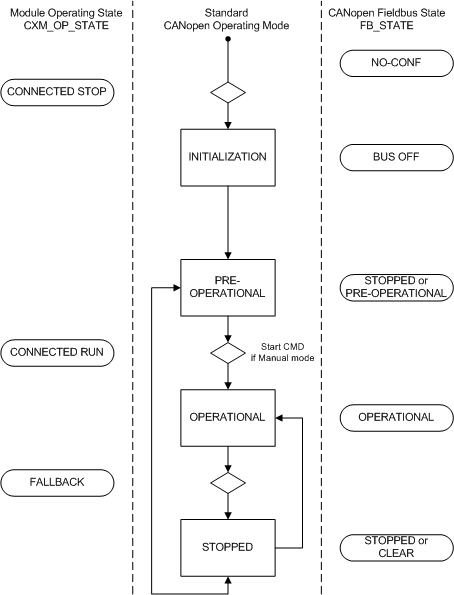
The BMECXM module executes the initialization of the CANopen bus according to the Boot-up procedure. It is done when the BMECXM module is in CONNECTED STOP state.
During the CANopen bus initialization, only read accesses to the object dictionary of the CANopen master and slave devices are possible via the SDO command interface.
|
|
PRE-OPERATIONAL
|
The boot-up sequence is now completed. In this state, no command has been received to enter in OPERATIONAL state.
The CANopen slave devices respond to SDO and NMT messages but not to PDOs.
|
|
OPERATIONAL
|
This is the main state of the CANopen bus.
In this state:
NOTE: If the BMECXM module is configured in manual mode, the EM_start command is mandatory to reach the OPERATIONAL state. |
|
STOPPED
|
In this state, only the slave monitoring is active. No service is available to read or write SDO.
|
|
BMECXM Operating State
|
Fieldbus Operating State
|
EtherNet/IP State
|
|---|---|---|
|
IDLE
|
IDLE
|
There is no connection
|
|
UNCONFIGURED
|
NO-CONF
|
|
|
CONFIGURED
|
BUS OFF
|
|
|
CONNECTED STOP
|
PRE OPERATIONAL
|
The connection is running
|
|
CONNECTED RUN
|
|
|
|
FALLBACK
|
Fallback strategy:
|
Depending on the I/O scanner type:
|
|
FW UPGRADE
|
Not applicable
|
There is no connection. The connection is aborted if existing.
|
(1)Switching form one state to an other one is done via an NMT command. (2)The CANopen fieldbus state stay in OPERATIONAL but with the last data received from the PLC. (3)CANopen master and slaves switch to STOPPED state. (4)The CANopen fieldbus state stay in OPERATIONAL but with data set to zero. |
||
|
Object
|
INITIALIZATION
|
PRE-OPERATIONAL
|
STOPPED
|
OPERATIONAL
|
|---|---|---|---|---|
|
PDO
|
–
|
–
|
–
|
Yes
|
|
SDO
|
–
|
Yes
|
–
|
Yes
|
|
SYNC
|
–
|
Yes
|
–
|
Yes
|
|
EMCY
|
–
|
Yes
|
–
|
Yes
|
|
Bootup
|
Yes
|
–
|
–
|
–
|
|
NMT
|
–
|
Yes
|
Yes
|
Yes
|
–Communication object not allowed. |
||||