|
Configuration Using Control Expert
|
|
|
Original instructions
|
|
Step
|
Action
|
|---|---|
|
1
|
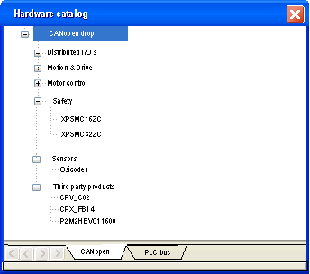
Access the CANopen bus configuration screen.
|
|
2
|
Double-click the slave to be configured.
|
|
3
|
Configure the usage function using the Configuration tab.
|
|
4
|
Configure the PDOs using the PDO tab.
|
|
5
|
Select the control of error detected using the Error control tab.
|
|
6
|
Configure the bootup procedure using the Bootup tab.
|
|
7
|
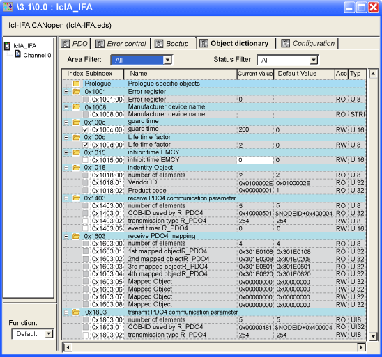
Integrate a third-party product using the Object Dictionary tab.
|
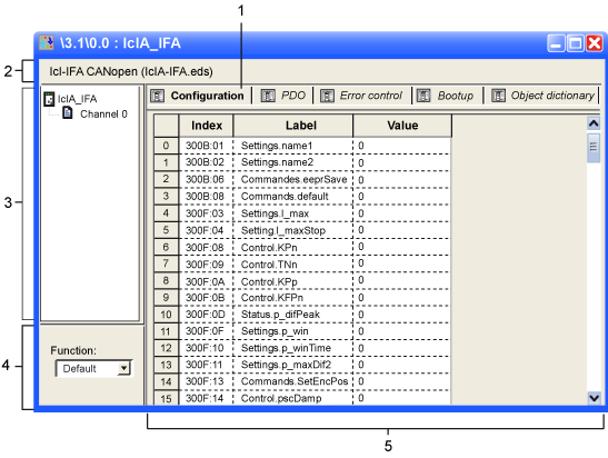
|
Number
|
Element
|
Function
|
|---|---|---|
|
1
|
Tabs
|
Indicates the type of window displayed. In this case, it is the configuration window.
|
|
2
|
Module
|
Indicates the device shortened name.
|
|
3
|
CANopen communication
|
Allows you to select the device and display the Overview tab. It gives the characteristics of the device.
|
|
Allows you to select the channel and display these tabs:
|
||
|
4
|
General parameters
|
Allows you to select the slave functions.
|
|
5
|
Configuration
|
Allows you to set up the channels of the devices.
NOTE: Some devices can be configured with an external tool. In this case, the configuration is stored in the device and you cannot enter configuration parameters because this field is empty. |
|
Number
|
Element
|
Function
|
|---|---|---|
|
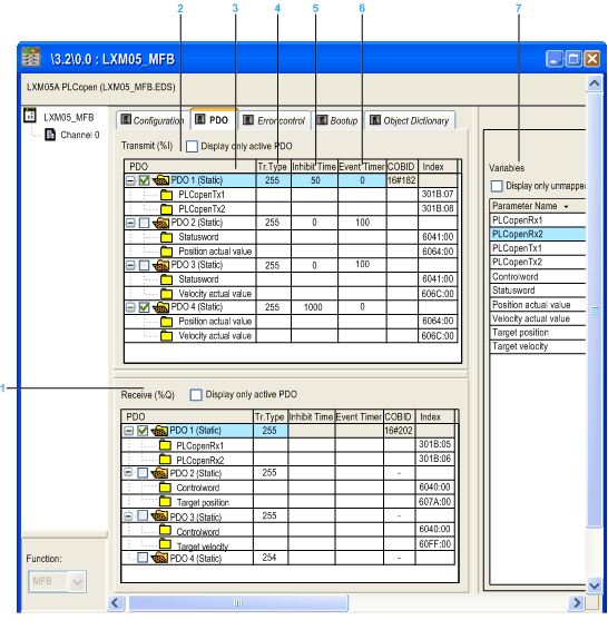
1
|
Receive (%Q)
|
Information received by the slave from the master.
|
|
2
|
Transmit (%I)
|
Information transmitted by the slave to the master.
|
|
3
|
PDO
|
|
|
4
|
Tr.Type
|
The transmission type can be:
NOTE: Verify that the configured transmission type is supported by the selected device. |
|
5
|
InhibitTime
|
Mask the communication during this time.
|
|
6
|
Event Timer
|
Time to manage an event in order to start a PDO.
|
|
7
|
Variables
|
Variables can be mapped to the PDOs.
To assign a variable to a PDO, drag and drop the variable into the desired PDO. A variable cannot be assigned with a static PDO.
|
|
If an object is mapped...
|
Then ...
|
|---|---|
|
In more than one RPDO of a node
|
It is not supported.
|
|
In an RPDO and in a TPDO of a node
|
It is represented by two network variables in both process images.
|
|
In more than one TPDO of a node
|
Each instance is linked to the same network variable.
|

 WARNING WARNING |
|
UNEXPECTED DIAGNOSTIC BEHAVIOR
Failure to follow these instructions can result in death, serious injury, or equipment damage.
|
|
Protocol Used
|
Function
|
|---|---|
|
Node Guarding
|
Monitoring of network nodes:
The concerned node answers in a given lapse time defined as below: lifetime = Guard Time * Life Time Factor
NOTE: If there is no connection monitoring during the lifetime interval, the CANopen slave device signals an error. |
|
Heartbeat
|
Mechanism that consists on sending cyclical presence messages generated by a heartbeat producer (CANopen slave) and the Heartbeat consumer (BMECXM) surveys the Heartbeat message reception.
NOTE:
|
 WARNING WARNING |
|
UNEXPECTED EQUIPMENT OPERATION
Manually verify all deactivated standard checks on the device before operating the system.
Changing the default parameters of the Bootup tab bypasses standard system checks.
Failure to follow these instructions can result in death, serious injury, or equipment damage.
|
|
Type
|
Functionality
|
|
|---|---|---|
|
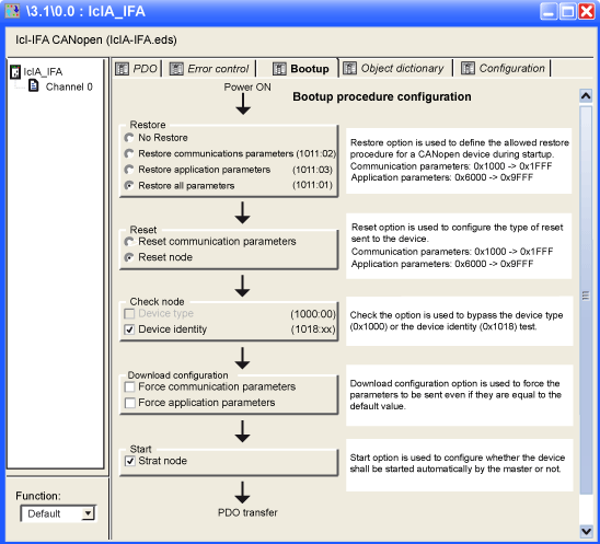
Restore
|
No Restore
|
–
|
|
Restore communication parameters
|
Enabled option according to the object 0x1011sub02. If checked, all parameters between 0x1000 to 0x1FFF are restored.
|
|
|
Restore application parameters
|
Enabled option according to the object 0x1011sub03. If checked and if the device correctly implements the service, all application parameters are restored.
|
|
|
Restore all parameters
|
Enabled option according to the object 0x1011sub01. If checked, all parameters are restored to default value.
|
|
|
Reset
|
Reset communication parameters
|
Option always enabled. If checked, all communication parameters are reset.
|
|
Reset node
|
Option always enabled. If checked, all parameters are reset.
|
|
|
Check node
|
Device type
|
If the device type identification value for the slave in object dictionary 0x1F84 is not 0x0000 ("don’t care"), compares it to the actual value.
NOTE: If unchecked, this option forces the object dictionary 0x1F84 to 0x0000. |
|
Device identity
|
If the configured vendor ID in object dictionary 0x1F85 is not 0x0000 ("don’t care"), read slave index 0x1018, sub-Index 1 and compare it to the actual value.
The same comparison is done for ProductCode, RevisionNumber, and SerialNumber according to object 0x1F86-0x1F88.
NOTE: If unchecked, this option forces the object dictionary 0x1F86-0x1F88 (sub device node ID) to 0x0000. |
|
|
Download Configuration
|
Force communication parameters
|
Forces the download of communication or configuration parameters (unchecked by default).
If the option is:
|
|
Force application parameters
|
||
|
Start
|
Start node
|
If the option is:
|
 WARNING WARNING |
|
UNEXPECTED EQUIPMENT OPERATION
Manually verify all Object Dictionary values and mapping.
Changing the default values and mapping of the Object Dictionary table generates non-standard behavior of the equipment.
Failure to follow these instructions can result in death, serious injury, or equipment damage.
|
|
Element
|
Function
|
|---|---|
|
Parameter
|
If the check box associated to each parameter is:
NOTE: To prevent programming redundancies or conflicts, parameters that can be modified in Configuration, PDO, or Error Control tabs are grayed out. |
|
Current Value
|
Modify the current value of an object (except read-only objects) by typing a value in the box. By default, the object is sent if the current value is modified. You can block object sending by deactivating the check box.
|
|
Default Value
|
Set objects to a specific value just before (prolog) or just after (epilog) the standard bootup procedure.
|
|
Area Filter
|
|
|
Status Filter
|
|