|
Adding Slave Devices on the CANopen Bus
|
|
|
Original instructions
|
|
Step
|
Action
|
|---|---|
|
1
|
|
|
2
|
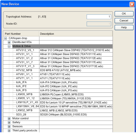
Double-click the connection point, where the module should be connected.
Result: the New Device window is displayed.
 |
|
3
|
In the Topological Address field, type the number of the connection point corresponding to the address.
NOTE: By default, the Control Expert software offers the first free consecutive address. |
|
4
|
From the CANopen drop, expand (+) the family to select your CANopen device.
|
|
5
|
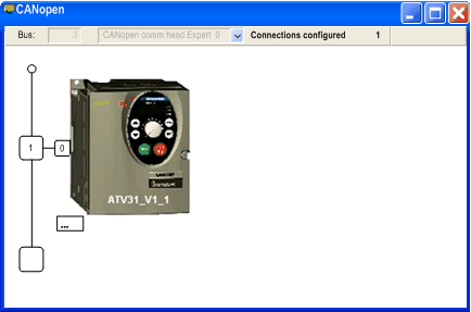
Click OK.
Result: the module is declared.
 |

|
Number
|
Element
|
Function
|
|---|---|---|
|
1
|
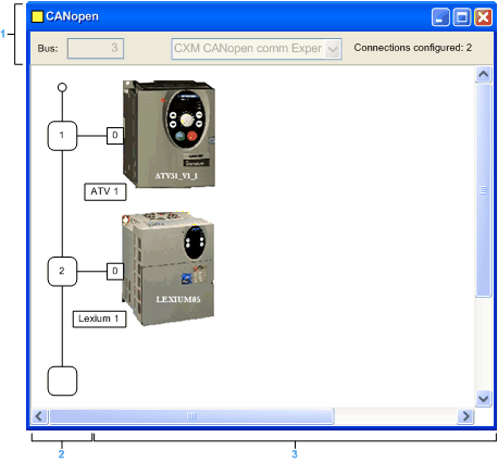
Bus
|
Bus number
|
|
Connections configured
|
Indicates the number of connection points configured.
|
|
|
2
|
Logical address area
|
Includes the addresses of the devices connected to the bus.
|
|
3
|
Module area
|
Includes the devices that are connected to the bus.
|