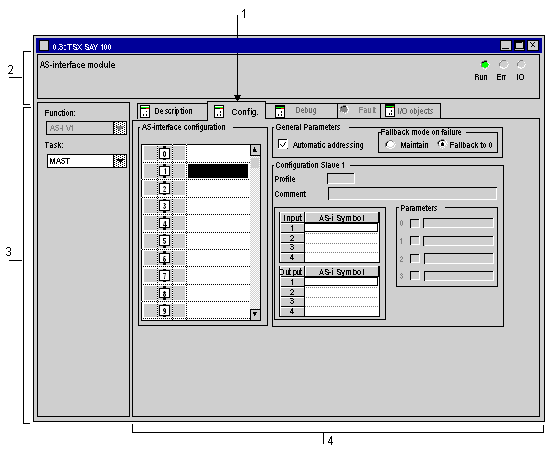
Description of the AS-i communication module configuration screen
(Original Document)
At a Glance
The configuration screen is a graphics tool used to configure a module selected in a rack. It gives access to the parameters associated with the module and the slave devices.
Illustration
The figure below represents a configuration screen.
Description
The following table shows the different elements of the configuration screen and their functions.
Address
Item
Function
1
Tabs
The front tab indicates the mode in progress (Configuration for this example). Each mode can be selected with the corresponding tab. Possible modes are:
  • Configuration,
  • Debug (or diagnostics), only accessible in online mode,
  • Diagnostics (Default), accessible only in Online mode.
The tab I/O Objects is used to presymbolize the input/output objects.
2
module zone
Specify the abbreviated title of the module and the status of the module in online mode
There are three indicators in the same zone that provide the status of module in online:
  • RUN indicates the operating mode of the module.
  • ERR signals an internal fault in the module.
  • I/O signals an external fault in the module or an application fault.
3
General parameters zone
makes it possible to select the general parameters associated with the channel :
  • Function : the Bus AS-i function is frozen (grayed).
  • Task: defines the MAST or FAST task through which the channel's implicit exchange objects will be exchanged.
4
configuration field
Makes it possible to configure the channel configuration parameters. Certain choices may be frozen and appear grayed.
It is broken down into four fields:
  • AS-interface configuration,
  • the selected slave characteristics,
  • the parameters applied to the chosen slave,
  • the input and output symbols associated with a device.