|
The BMX EIA 0100 Configuration Screen
|
|


|
Original instructions
|
|
The BMX EIA 0100 Configuration Screen
|
|
|
Original instructions
|
|
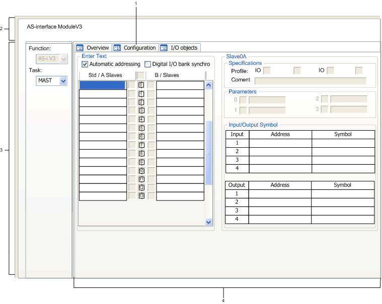
Number
|
Item
|
Function
|
|---|---|---|
|
1
|
Tabs
|
The front tab indicates the current mode (Config. for this example). Each mode can be selected using the corresponding tab.
Possible modes are:
NOTE: The tab I/O Objects is used to preview the Input/Output objects. |
|
2
|
Module
|
This zone specifies the abbreviated title of the module and the status of the module in Connected mode
There are three indicators in the this zone that indicates the status of module while Connected:
|
|
3
|
General parameters
|
In this zone select the general parameters associated with the channel:
|
|
4
|
Configuration
|
These fields are used to configure the channel configuration parameters. Certain choices may not be available (grayed out).
There are four fields:
|
