The BMX ART 0414/814 modules are multi-range acquisition devices with four inputs for the BMX ART 0414 and eight inputs for the BMX ART 0814.
Both Modules offer the following ranges for each input, according to the selection made during configuration:
-
RTD: IEC Pt100, IEC Pt1000, US/JIS Pt100, US/JIS Pt1000, Copper CU10, Ni100 or Ni1000
-
thermocouple: B, E, J, K, L, N, R, S, T or U,
-
voltage: +/- 80 mV, +/- 80 mV, +/- 160 mV, +/- 320 mV, +/- 640 mV, +/- 1.28 V,
-
ohms: 0..400 Ω, 0..4000 Ω.
NOTE: The TELEFAST2 accessory referenced ABE-7CPA412 facilitates connection and provides a cold junction compensation device.
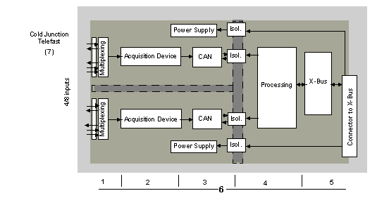
The BMX ART 0414/0814 input modules perform the following functions.
Details of the functions are as follows.
|
Address
|
Element
|
Function
|
|
1
|
Adapting the Inputs
|
Adaptation consists in a common mode and ifferential mode filter. Protection resistors on the inputs allowt to withstand voltage spikes of up to +/- 7.5 V.
A layer of multiplexing allows self-calibration of the acquisition device offset, as close as possible to the input terminal, as well as selecting the cold junction compensation sensor included in the TELEFAST housing.
|
|
2
|
Amplifying Input Signals
|
Built around a weak-offset amplifier internal to the A/N converter.
A current generator ensures the RTD resistance measurement.
|
|
3
|
Conversion
|
The converter receives the signal issued from an input channel or from the cold junction compensation. Conversion is based on a Σ Δ 16 -bit converter. There is a converter for each input.
|
|
4
|
Transforming incoming values into workable measurements for the user
|
-
recalibration and alignment coefficients to be applied to measurements, as well as the module's self-calibration coefficients
-
(numeric) filtering of measurements, based on configuration parameters
-
scaling of measurements, based on configuration parameters
|
|
5
|
Communicating with the Application
|
-
manages exchanges with CPU.
-
topological addressing
-
receiving configuration parameters from module and channels
-
sending measured values, as well as module status, to the application
|
|
6
|
Module monitoring and sending error notification back to application
|
|
|
7
|
Cold Junction Compensation
|
-
internal compensation using the TELEFAST ABE-7CPA412
-
external compensation by Pt100
-
external compensation using the CJC values of channels 4/7 for channels 0/3. In this case, only one sensor is needed
|
Display of Electrical Range Measurements
Measurements may be displayed using standardized display (in %, to two decimal places).
|
Type of Range
|
Display
|
|
Bipolar range
|
from -10,000 to +10,000 (-100.00 % to +100.00 %)
|
It is also possible to define the range of values within which measurements are expressed, by selecting:
These lower and upper thresholds are integers between -32,768 and 32,768.
Display of Temperature Range Measurements
Measurements provided to the application are directly usable. It is possible to choose either "In Temperature" Display or Standardized Display:
-
for "In Temperature" display mode, values are provided in tenths of a degree (Celsius or Fahrenheit, depending on the unit you have selected).
-
for the user-specified display, you may choose a Standardized Display 0...10,000 (meaning from 0 to 100.00 %), by specifying the minimum and maximum temperatures as expressed in the 0 to 10,000 range.
The type of filtering performed by the system is called "first order filtering". The filtering coefficient can be modified from a programming console or via the program.
The mathematical formula used is as follows:
where:
α = efficiency of the filter
Mesf(n) = measurement filtered at moment n
Mesf(n-1) = measurement filtered at moment n-1
Valg(n) = gross value at moment n
You may configure the filtering value from 7 possibilities (from 0 to 6). This value may be changed even when the application is in RUN mode.
NOTE: Filtering may be accessed in Normal or Fast Cycle.
The filtering values are as follows. They depend on the sensor type. T is a cycle time of 200 ms for TC and mV. T is also a cycle time of 400 ms for RTD and Ohms.
|
Desired Efficiency
|
Required Value
|
Corresponding α
|
Filter Response Time at 63%
|
Cut-off Frequency (in Hz)
|
|
No filtering
|
0
|
0
|
0
|
0
|
|
Low filtering
|
1
2
|
0.750
0.875
|
4 x T
8 x T
|
0.040 / T
0.020 / T
|
|
Medium filtering
|
3
4
|
0.937
0.969
|
16 x T
32 x T
|
0.010 / T
0.005 / T
|
|
High filtering
|
5
6
|
0.984
0.992
|
64 x T
128 x T
|
0.025 / T
0.012 / T
|
The values may be displayed using standardized display (in %, to two decimal places).
|
Type of Range
|
Display
|
|
Unipolar range
|
from 0 to 10,000 (0 % at +100.00 %)
|
|
Bipolar range
|
from -10,000 to 10,000 (-100.00 % to +100.00 %)
|
The user may also define the range of values within which measurements are expressed, by selecting:
These lower and upper thresholds are integers between -32,768 and +32,767.
Main frequency 50/60 Hz Rejection
Depending on the country, the user can configure the frequency rejection of main power harmonics by adapting the speed of sigma delta converter.
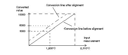
The process of "alignment" consists in eliminating a systematic offset observed with a given sensor, around a specific operating point. This operation compensates for an error linked to the process. Therefore, replacing a module does not require a new alignment. However, replacing the sensor or changing the sensor's operating point does require a new alignment.
Conversion lines are as follows:
The alignment value is editable from a programming console, even if the program is in RUN Mode. For each input channel, you can:
-
view and modify the desired measurement value.
-
save the alignment value.
-
determine whether the channel already has an alignment.
The alignment offset may also be modified through programming.
Channel alignment is performed on the channel in standard operating mode, without any effect on the channel's operating modes.
The maximum offset between measured value and desired (aligned) value may not exceed +/-1,500.
NOTE: To align several analog channels on the BMX ART/AMO/AMI/AMM modules, we recommand proceeding channel by channel. Test each channel after alignment before moving to the next channel in order to apply the parameters correctly.


