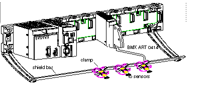
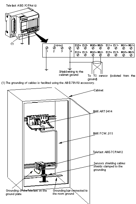
In order to protect the signal from outside interference induced in series mode and interference in common mode, we recommend that you take the following precautions.
-
Connection at the FCN connectors:
Given that there are a large number of channels, a cable of at least 10 twisted pairs is used, with general shielding (outside diameter 10 mm maximum), fitted with one or two male 40-pin FCN connectors for direct connection to the module.
Connect the cable shielding to the grounding bar. Clamp the shielding to the grounding bar on the module side. Use the
shielding connection kit BMXXSP•••• to connect the shielding.
In order for the acquisition system to operate correctly, we recommend you take the following precautions:
-
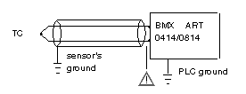
if sensors are isolated from ground, all the shields of the sensor cables must be referenced to the Telefast/PLC ground.
-
if sensors are referenced to the sensor ground which is far from PLC ground, all the shields of the sensor cables must be referenced to the sensors ground to eliminate the ground loop path.
Using the Sensors Isolated from the Ground
The sensors are connected according to the following diagram:
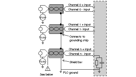
If the sensors are referenced in relation to the ground, this may in some cases return a remote ground potential to the terminals or the FCN connector. It is therefore essential to follow the following rules:
-
the potential must be less than the permitted low voltage: for example, 30 Vrms or 42.4 VDC.
-
setting a sensor point to a reference potential generates a leakage current. You must therefore check that all leakage currents generated do not disturb the system.
Sensors and other peripherals may be connected to a grounding point some distance from the module. Such remote ground references may carry considerable potential differences with respect to local ground. Induced currents do not affect the measurement or integrity of the system.
Electromagnetic Hazard Instructions
 DANGER


 DANGER
  CAUTION