Creation and Use of the DFBs
Original instructions
At a Glance
DFB types are function blocks that can be programmed by the user ST, IL, LD or FBD. Our example uses a motor DFB and a valve DFB.
We will also be using existing DFB from the library for monitoring variables. Particularly "safety" variables for tank levels, and "error" variables returned by the valve. The status of these variables will be visible in Diagnostics display.
NOTE: Function blocks can be used to structure and optimize your application. They can be used whenever a program sequence is repeated several times in your application, or to set a standard programming operation (for example, an algorithm that controls a motor).
Once the DFB type is created, you can define an instance of this DFB via the variable editor or when the function is called in the program editor.
NOTE: For more information, refer to chapter User Function Blocks (DFB).
Procedure for Creating a DFB
The table below shows the procedure for creating application DFBs.
Step
Action
1
In the Project browser, right click on Derived FB types and select Open.
2
In the Data editor window, select the box in the Name column and enter a name for your DFB and confirm with Enter. The name of your DFB appears with the sign "Works" (unanalyzed DFB).
3
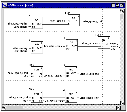
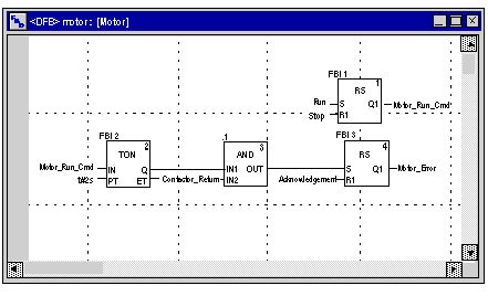
Open the structure of your DFB (see figure next page) and add the inputs, outputs and other variables specific to your DFB.
4
When the variables of the DFB are declared, analyze your DFB (the sign "Works" must disappear). To analyze your DFB, select the DFB and, in the menu, click Build then Analyze. You have created the variables for your DFB, and must now create the associated section.
5
In the Project browser, double-click on Derived FB types then on your DFB. Under the name of your DFB, the Sections field will appear.
6
Right click on Sections then select New section.
7
Give your section a name, then select the language type and confirm with OK. Edit your section using the variables declared in step 3. Your DFB can now be used by the program (DFB Instance).
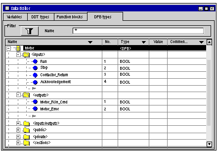
Variables Used by the Motor DFB
The following table lists the variables used by the Motor DFB.
Variable
Type
Definition
Run
Input
Motor run command.
Stop
Input
Motor stop command.
Contactor_Return
Input
Contactor feedback in the event of motor run problem.
Acknowledgement
Input
Acknowledgement of the Motor_error output variable.
Motor_Run_Cmd
Output
Start of motor.
Motor_Error
Output
Display in the "Diagnostics display" window of an alarm linked to a problem with the motor.
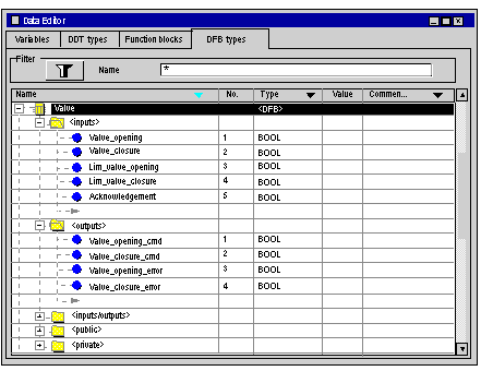
Illustration of the Motor DFB Variables Declared in the Data Editor
The following screen shows the Motor DFB variables used in this application to control the motor.
Operating Principle of the Motor DFB
The following screen shows the Motor DFB program written by the application in FBD for controlling the motor.
When Run = 1 and Stop = 0, the motor can be controlled (Motor_Run_Cmd = 1). The other part monitors the Contactor_return variable. If Contactor_return is not set to "1" after the Discrete counter counts two seconds, the Motor_error output switches to "1".
NOTE: For more information on creating a section, refer to chapter Programming and select the required language).
Variables Used by the Valve DFB
The following table lists the variables used by the Valve DFB.
Variable
Type
Definition
Valve_opening
Input
Valve opening command.
Valve_closure
Input
Valve closure command.
Lim_valve_opening
Input
Status of valve limit.
Lim_valve_closure
Input
Status of valve limit.
Acknowledgement
Input
Acknowledgement of variables Valve_closure_error or Valve_opening_error.
Valve_opening_cmd
Output
Opening of the valve.
Valve_closure_cmd
Output
Closure of the valve.
Valve_opening_error
Output
Display in the "Diagnostics display" window of an alarm linked to a problem with the valve opening.
Valve_closure_error
Output
Display in the "Diagnostics display" window of an alarm linked to a problem with the valve closure.
Illustration of the Valve DFB Variables Declared in the Data Editor
The following screen shows the Valve DFB variables used in this application to control the valve.
Operating Principle of the Valve DFB
The following screen shows the Valve DFB written in FBD language.
This DFB authorizes the command to open the valve (Valve_opening_cmd) when the inputs Valve_closure and Lim_valve_opening are set to "0". The principle is the same for closure, with an additional safety feature if the user requests the opening and closing of the valve at the same time (opening takes priority).
In order to monitor opening and closing times, we use the TON timer to delay the triggering of an error condition. Once the valve opening is enabled (Valve_opening_cmd = 1), the timer is triggered. If Lim_valve_opening does not switch to "1" within two seconds, the output variable Valve_opening_error switches to "1". In this case a message is displayed.
NOTE: The PT time must be adjusted according to your equipment.
NOTE: For more information on creating a section, refer to chapter Programming and select the required language).