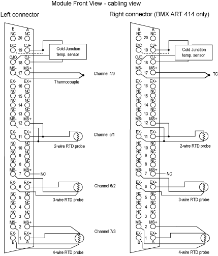
The BMX ART 0414 input module consists of a 40-pin FCN connector.
The BMX ART 0814 input module consists of two 40-pin FCN connectors.
Connector Pin Assignment and Sensors Wiring
This example uses a probe configuration with:
The pin assignment for the 40-pin FCN connector and the sensors wiring is shown below:
MS+:
RTD Measure + input / Thermocouple + input
MS-:
RTD Measure - input / Thermocouple - input
EX+:
RTD probe current generator + output
EX-:
RTD probe current generator - output
NC:
Not connected
DtC:
The CJC sensor detection input is connected to CJ+ if the sensor type is DS600. It is not connected (NC) if the sensor type is LM31.
NOTE: The CJC sensor is needed for TC only.
Cold Junction Compensation
For each block of 4 channels (channels 0 to 3 and channels 4 to 7), the external compensation of the module is performed in the TELEFAST ABE-7CPA412 accessory. This device provides a voltage in mV corresponding to:
Voltage = (6.45 mV * T) + 509 mV (where T = temperature in °C).
The overall margin of error when using this device is reduced to 1.2°C in the -5°C to +60°C temperature range.
It is possible to increase the precision of the compensation by using a 2/3-wires Pt100 probe directly connected to channels 0 and 4 (only for the BMX ART0814) on the module or connected to the TELEFAST terminal blocks. Channel 0 is thus dedicated to the cold junction compensation of channels 1, 2 and 3. channel 4 is thus dedicated to channels 4 to 7.
It is also possible, by using a 2-wire Pt100 probe, provided the initial length of the probe is limited, to maintain channel 0 as a thermocouple input.
The wiring would then look like this:
The wiring is only valid if the channel 0 is used. If the channel 0 is not used, select a cold junction with external Pt100. The range of the channel 0 is changed to a 3-wires Pt100 probe.
The wiring would then look like this:
NOTE: For the BMX ART 0814 Module, the CJC values of channels 4 to 7 can also be used for channels 0 to 3. Therefore, only one external
CJC sensor is wired on channel 4.
 WARNING

