|
|
(Original Document)
|

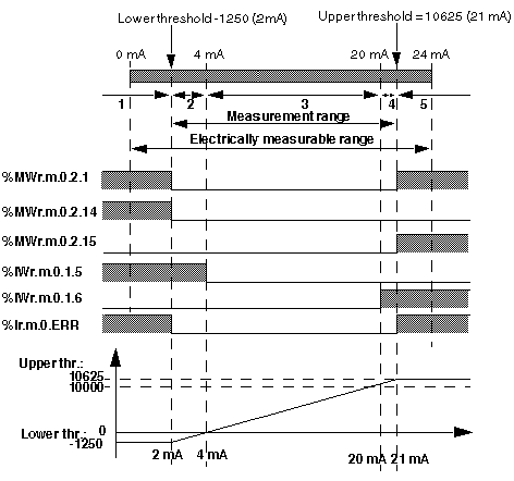
Nominal AreaMeasurement range matching the chosen range.
Upper Tolerance AreaValues included between the maximum value for the range (for instance: + 10 V for the -10 V +10 V range) and the upper threshold.
Lower Tolerance AreaValues included between the minimum value for the range (for instance: - 10 V for the -10 V +10 V range) and the lower threshold.
Overflow AreaArea located beyond the upper threshold.
Underflow AreaArea located below the lower threshold.
|
Bit Name
|
Meaning (when = 1)
|
|---|---|
|
%IWr.m.c.1.5
|
Measurement in Lower Tolerance Area
|
|
%IWr.m.c.1.6
|
Measurement in Upper Tolerance Area
|
|
%MWr.m.c.2.1
|
If over/underflow control is required, this bit indicates any offending variation from range :
|
|
%Ir.m.c.ERR
|
Channel Fault.
|
|
Range
|
Lower Tolerance Area
|
Upper Tolerance Area
|
||||
|---|---|---|---|---|---|---|
|
-
|
Default Value
|
Maximum Value
|
Min. Value
|
Default Value
|
Min. Value
|
Maximum Value
|
|
Bipolar
|
-0,125 x Δrange/2
|
0
|
-0,25 x Δrange/2
|
-0,125 x Δrange/2
|
0
|
0,25 x Δrange/2
|
|
Unipolar
|
-0,125 x Δrange
|
0
|
-0,25 x Δrange
|
0,125 x Δrange
|
0
|
0,25 x Δrange
|
|
Normalized Bipolar
|
-1250
|
0
|
-2500
|
1250
|
0
|
2500
|
|
Normalized Unipolar
|
-1250
|
0
|
-2500
|
1250
|
0
|
2500
|
|
User Bipolar
|
-0,125 x Δrange/2
|
0
|
-0,25 x Δrange/2
|
0,125 x Δrange/2
|
0
|
0,25 x Δrange/2
|
|
User Unipolar
|
-0,125 x Δrange
|
0
|
-0,25 x Δrange
|
0,125 x Δrange
|
0
|
0,25 x Δrange
|
|
Legend:
|
||||||
|
Δrange
|
Range Upper Value - Range Lower Value
|
|||||

1Underflow Area.
2Lower Tolerance Area
3Nominal Area.
4Upper Tolerance Area
5Overflow Area