Grounding the Rack and Power Supply Module
Original instructions
Overview
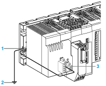
The following illustration shows how to ground the rack and the power supply module:
1 
Protective earth screw of the rack
2 
Earthing of the installation (i.e., cabinet)
3 
Functional ground (FG) terminal of the power supply module.
NOTE: Ground every racks and power supply modules in the PAC system.
Grounding Rules
To ground the rack and the power supply module:
The protective earth screw of the rack is located on the left-hand side of the rack, close to the power supply module.
DANGER
HAZARD OF ELECTRIC SHOCK
Connect the protective earth screw of the rack to the earthing of the installation.
Failure to follow these instructions will result in death or serious injury.
DANGER
HAZARD OF ELECTRIC SHOCK
  • Connect the functional ground (FG) terminal of the power supply module directly to the protective earth screw of the rack.
  • Do not chain the function ground (FG) terminals of redundant power supply modules together.
  • Do not connect anything else to the functional ground (FG) terminal of the power supply module.
Failure to follow these instructions will result in death or serious injury.
The ends of the cables connected to the protective earth screw of the rack must have ring or spade connectors that maintain an electrical connection when the screw is loose.
The tightening torque for the protective earth screw is 1.2 N•m (0.88 lbf-ft).
DANGER
LOOSE WIRING CAUSES ELECTRIC SHOCK
  • Use only cables with ring or spade lugs to connect the protective earth screw of the rack and check that there is a good ground connection.
  • Make sure that the protective earth screw of the rack is tightened properly.
Failure to follow these instructions will result in death or serious injury.
The following table gives the ring and spade lugs characteristics to connect ground cables to the M4 protective earth screw of the rack:
øA
øB
L(*)
ø
L1
L2(*)
mm
4.34
≤ 8.8
≥ 6.2
4.34
≤ 9.8
≥ 6.2
in.
0.171
≤ 0.346
≥ 0.245
0.171
≤ 0.385
≥ 0.245
Refer to the chapter Wiring Rules for power supply terminal block connections.
Equipotential Grounding System
When developing an M580 Hot Standby system, confirm that all equipment is grounded to the same potential. This includes, for example, the primary and the standby Hot Standby local racks, plus all connected RIO drops and distributed equipment. To accomplish this, confirm that you have an equipotential grounding system in place.