|
|
Original instructions
|

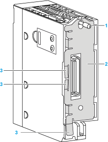
1Mounting screw
2Grounding plate
3Contact strips
  DANGER DANGER |
|
HAZARD OF ELECTRIC SHOCK
Check that ground contact strips are available and not bent out of shape.
Failure to follow these instructions will result in death or serious injury.
|
  DANGER DANGER |
|
HAZARD OF ELECTRIC SHOCK
Remove all power sources before installing the rack extender module.
Failure to follow these instructions will result in death or serious injury.
|
|
Step
|
Action
|
|
|---|---|---|
|
1
|
Remove all power sources to the rack.
|
|
|
2
|
Using the microswitches on the side of the rack extender module, set a unique address for that rack from 00 to 08. Confirm that the address assigned to each extended rack is unique with respect to all other extended racks.
|
|
|
3
|
Remove the protective cover from the connector of the module slot labeled XBE (rightest module slot of the rack).
|
|
|
4
|
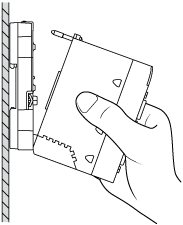
Position the locating pin at the rear of the module (lower part of the module) in the centering hole of the module slot labeled located XBE.
Swivel the module towards the top of the rack so that the module sits flush with the rack.
Tighten the mounting screw to hold the module in place on the rack.
Tightening torque: 0.4...1.5 N•m (0.30...1.10 lbf-ft)
|
 |
 WARNING WARNING |
|
UNINTENDED EQUIPMENT OPERATION
Check that the mounting screw is securely tightened to ensure the module is firmly attached to the rack.
Failure to follow these instructions can result in death, serious injury, or equipment damage.
|
|
Step
|
Action
|
|
|---|---|---|
|
5
|
Connect each extended rack to the rack immediately before it and immediately after it using the appropriate extension cable.
|
|
|
6
|
Terminate the unused connector on the extender module in the main extended rack and the unused connector on the last extended rack. Use a line terminator labeled A/ on one end of the extended rack and a line terminator labeled /B on the other end of the extended rack.
|
|