|
Rack Extender Module Accessories
|
|
|
Original instructions
|
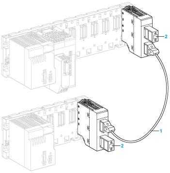
1extension cable
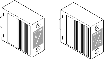
2line terminators
 CAUTION CAUTION |
|
INRUSH CURRENT
Insertion and extraction of an extension cable must only be done with all the station elements switched off (racks, PC, etc.)
Failure to follow these instructions can result in injury or equipment damage.
|
|
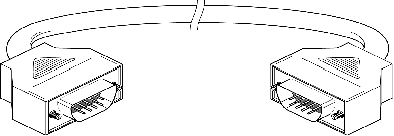
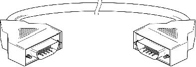
Cable reference
|
Length
|
|
|---|---|---|
|
Straight connectors
|
TSXCBY010K
|
1 m (3.28 ft)
|
|
TSXCBY030K
|
3 m (9.84 ft)
|
|
|
TSXCBY050K
|
5 m (16.40 ft)
|
|
|
TSXCBY120K
|
12 m (39.37 ft)
|
|
|
TSXCBY180K
|
18 m (59.05 ft)
|
|
|
TSXCBY280KT
|
28 m (91.86 ft)
|
|
|
Angled connectors
|
BMXXBC008K
|
0.8 m (2.63 ft)
|
|
BMXXBC015K
|
1.5 m (4.92 ft)
|
|
|
BMXXBC030K
|
3 m (9.84 ft)
|
|
|
BMXXBC050K
|
5 m (16.40 ft)
|
|
|
BMXXBC120K
|
12 m (39.37 ft)
|
|
 CAUTION CAUTION |
|
INRUSH CURRENT
Insertion or extraction of a line terminator must only be done with all the station racks switched off.
Failure to follow these instructions can result in injury or equipment damage.
|
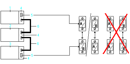
1X80 main rack
2first X80 extended rack
3last X80 extended rack
4BMXXBE1000 modules in each rack
5TSXTLYEX line terminator in the main rack and the last rack
6BMXXBC•••K or TSXCBY•••K extension cables between each rack
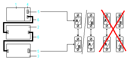
1X80 main rack
2first Premium extended rack
3last Premium extended rack
4BMXXBE1000 module
5TSXTLYEX line terminator in the main rack and the last rack
6BMXXBC•••K or TSXCBY•••K extension cables between each rack