This section presents the connection of direct current power supply modules to an alternating current network:
-
BMXCPS2010 (24 Vdc)
-
BMXCPS3020 (24...48 Vdc)
-
BMXCPS4022 (24...48 Vdc)
-
BMXCPS3540T (125 Vdc)
-
BMXCPS3522 (125 Vdc)
The power supply module is intended for use in low-voltage installations, in which the main power branch is protected on both wires by devices as fuses or breakers that limit the current to 15 A for North America and 16 A for the rest of the world. For details, refer to the description of
standards and certifications.
NOTE: The direct current power supply modules are already equipped with a protective fuse. This fuse, connected at input voltage, is inside the module and is not accessible.
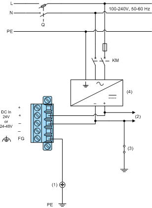
BMXCPS2010, BMXCPS3020, and BMXCPS4022 Wiring Diagram
The following diagram shows the 5-pin terminal block connections on to a grounded alternating current network:
(1)
Ground screw of the rack
(2)
Sensor power supply
(3)
Shielding connector kit
(4)
Minimum basic insulation AC/DC converter
FG
Functional ground
PE
Protective earth
N
Neutral
L
Phase
Q
General isolator
KM
Line contactor or circuit breaker
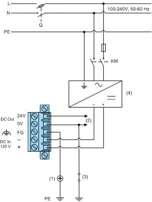
BMXCPS3540T Wiring Diagram
(1)
Ground screw of the rack
(2)
Sensor power supply
(3)
Shielding connector kit
(4)
Minimum basic insulation AC/DC converter
FG
Functional ground
PE
Protective earth
N
Neutral
L
Phase
Q
General isolator
KM
Line contactor or circuit breaker
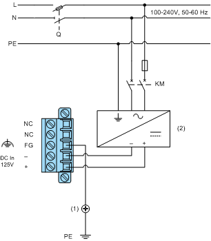
BMXCPS3522 Wiring Diagram
The following diagram shows the 5-pin terminal block connections on to a grounded alternating current network:
(1)
Ground screw of the rack
(2)
Minimum basic insulation AC/DC converter
NC
Not connected
FG
Functional ground
PE
Protective earth
N
Neutral
L
Phase
Q
General isolator
KM
Line contactor or circuit breaker 

